Verilink Access Manager 2000 (896-502037-001) Product Manual User Manual
Page 122
Configuring Access Manager
4-36
Access Manager 2000 User Manual
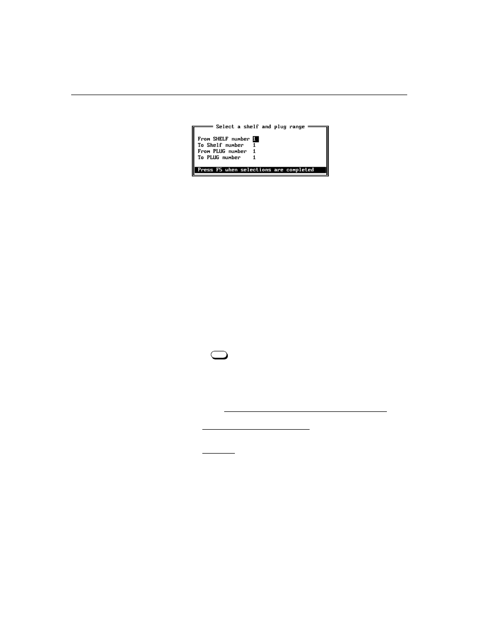
The Select a shelf and plug range screen appears.
Skip Steps 6 and 7 if the plug type is an NCC 2 0 20.
6. You can extend the range of shelves and plugs across different types
of modules. Only modules of the type that you’ve selected will
accept the download.
Slots (and consequently, plugs) are numbered from left to right. The
leftmost circuit element (that is, plug) in any shelf is always
numbered 1. The second slot is 2, and so on.
The shelf which includes the node controller is shelf number 1.
If the plug is in a multiline shelf, you must enter the same shelf
number you used when you set the shelf address during the initial
hardware installation.
Enter the shelf and range of slots in the fields.
Press to confirm the range.
7. If you enter an invalid shelf number or range of elements, an error
message appears. Re-enter the proper numbers.
8. Once you confirm the range, a warning message appears to let you
know that
once down-line loading begins, it cannot be aborted
.
a. If you’re sure you want to proceed with downline loading, type
Y
at the prompt.
b. Otherwise, press any key to exit from this operation.
9. Access Manager now downloads the new firmware to the selected
elements.
•
First, the circuit element reverts to its original firmware
(whatever’s in its EPROM) and its processor is reset. Once the
processor is reset, circuit elements perform functions (including
F5