Machine interface, Untitled – Hypertherm Phoenix 8.0 User Manual
Page 557
Edge Ti
550
Machine Interface
The information provided here is the basic information for connection of the shape
cutting control to the cutting table. Each machine interface will vary slightly based on
the cutting table configuration and features. Additionally, I/O pinout information may
vary slightly based on the configuration of the selected I/O and their locations. Changes
to the I/O configuration may be made in the password protected I/O screen. All controls
are shipped with a default selection of Inputs and interface locations for the selected
control Interface (I/O) configuration. Installation and service should only be performed
by a qualified service technician.
The rear panel of the control has several cable connectors to connect the control to power,
I/O and communication ports. These connectors are clearly labeled as to their function.
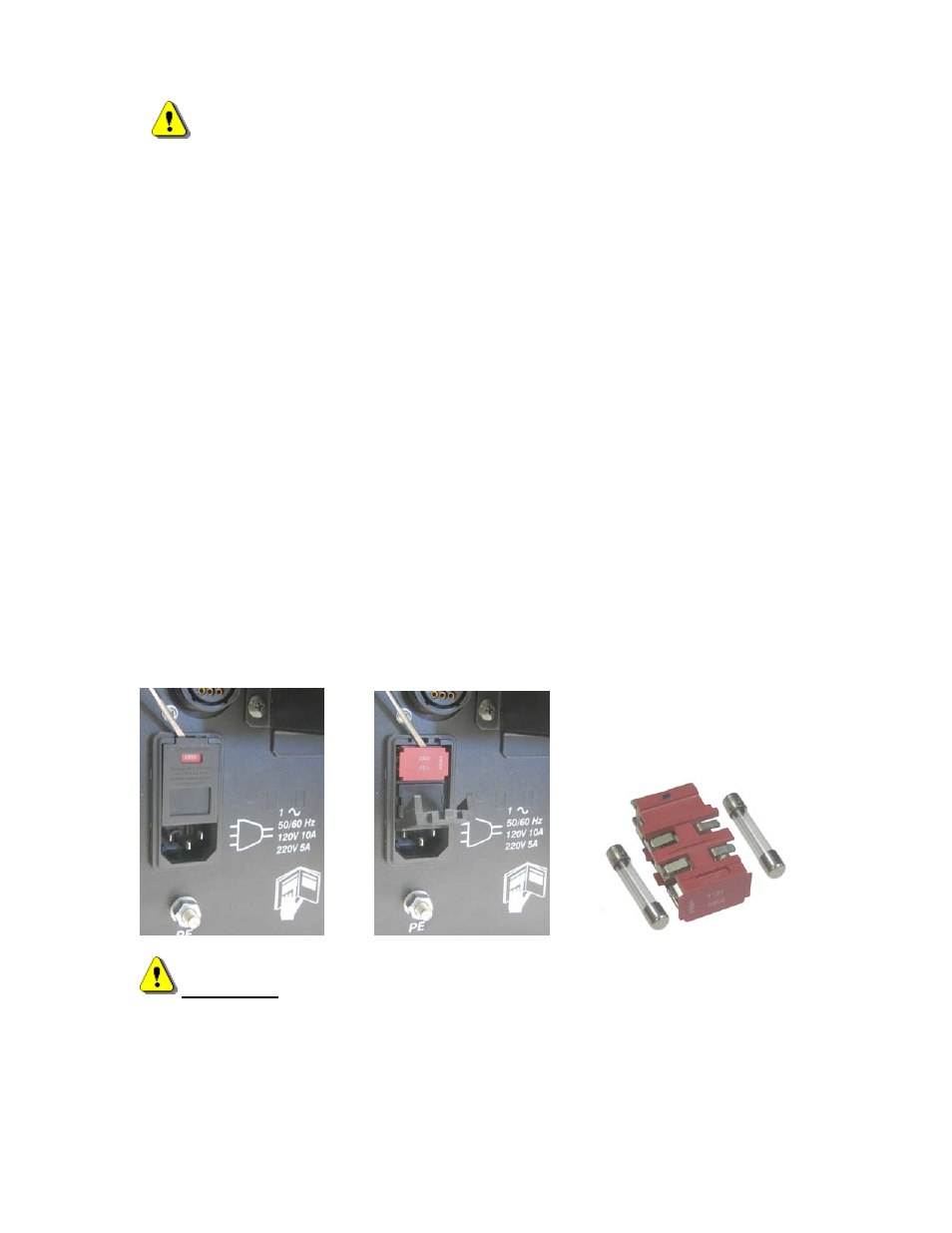
AC Input
The AC power cable is inserted into the AC power connector and plugged into a standard
3-way 115 or 230 volt outlet. The AC Power connector contains an integral fuse module
and line filter. AC input power can be selected by the user by changing position of the
fuse module so that the selected voltage is displayed.
WARNING! Ensure proper orientation of fuse module for input power before
applying power to the CNC. Component damage could occur with incorrect voltage
setting.
Recommended AC Fuses
Different fuse ratings are recommended based on incoming voltage selected.
Operation and maintenance of automated equipment involves potential hazards. Personnel
should take precautions to avoid injury. This equipment should only be opened by trained
service personnel.