Front panel layout – Hypertherm Phoenix 8.0 User Manual
Page 22
Overview
14
-
-
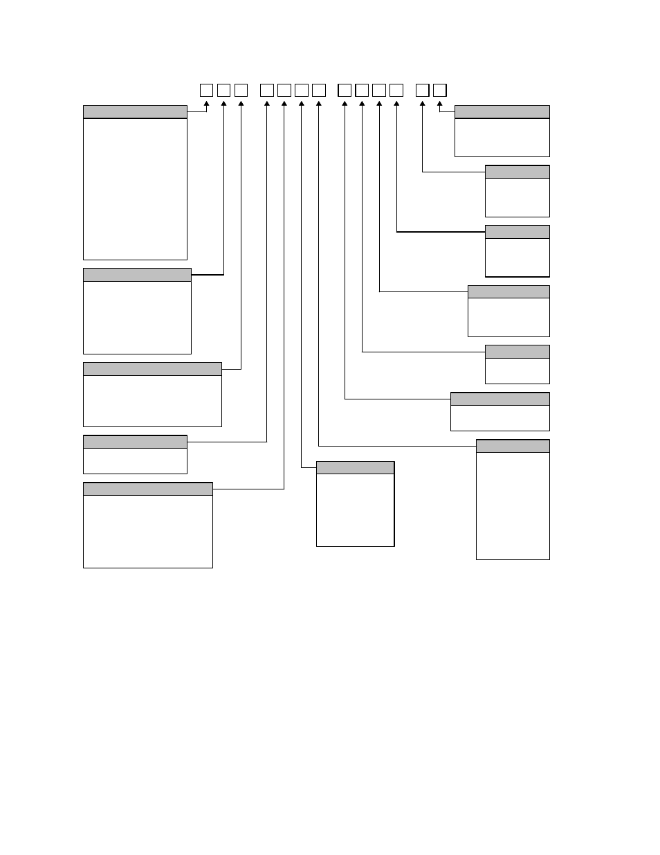
Axis Configuration
2 = 2 Servo Axes
3 = 3 Servo Axes
4 = 4 Servo Axes
5 = 5 Servo Axes
6 = 6 Servo Axes
7 = 7 Servo Axes
8 = 8 Servo Axes
9 = 9 Servo Axes
A = 10 Servo Axes
B = 11 Servo Axes
C = 12 Servo Axes
S = Sercos
I / O Configuration
B = Burny 3 / 5
M = MicroPath
P = PicoPath
V = Voyager
S = Sercos
D = Edge Ti - DC amps
Power Supplies
0 = Standard Logic Supply
2 = Standard Logic Supply &
Auxiliary Supply with
+5, +/-12 & +24 vdc
Pointing Device
0 = None
1 = Industrial Mouse
LCD Type
X = None
0 = 10.4" Dual Scan DSTN
1 = 10.4" Active Matrix TFT
2 = 15" Active Matrix TFT
3 = 15" Touch Screen
4 = 12.1" Active Matrix TFT
Memory
0 = 16 MBytes
1 = 32 MBytes
2 = 64 MBytes
3 = 128 MBytes
4 = 256 MBytes
5 = 512 MBytes
Processor
Backup Hard Drive
0 = None
1 = Installed
-
H
THC
0 = None
1 = 1 THC
2 = 2 THC's
Speed Pots
0 = None
1 = 1 Speed Pot
2 = 2 Speed Pots
Joystick
0 = None
1 = Joystick
Operating System
APC
0 = None
1 = Laser
2 = Plasma
0 = Windows 95 / 98
1 = Windows NT
2 = Windows XP
0 = 166 MHz
1 = 200 MHz
2 = 266 MHz
3 = 433 MHz
4 = 566 MHz
5 = 1.2 GHz
6 = 2.4 GHz
7 = 3.06 GHz
8 = 1.3 GHz M
Front Panel Layout
This software is designed specifically for 15” TFT Touch Screen operation with 1024 x 768 or
higher resolution and is used on all CNC models. Individual man machine interface (MMI) and
front panels may vary.
Power Switch
Hypertherm Automation controls are equipped with a momentary contact power switch. Press
briefly and release for controlled power on and power off the control. Pressing the power
switch for 10 seconds will force a hard system shutdown of Windows and the control.
Generally, a hard shutdown is not recommended.
Touch Screen