Comtech EF Data DMD20 User Manual
Page 41
DMD20/DMD50/DMD2050/DMD2050E/DMD1050/OM20 Remote Protocol
Remote Operations
MN-DMDREMOTEOP Revision 9
1–31
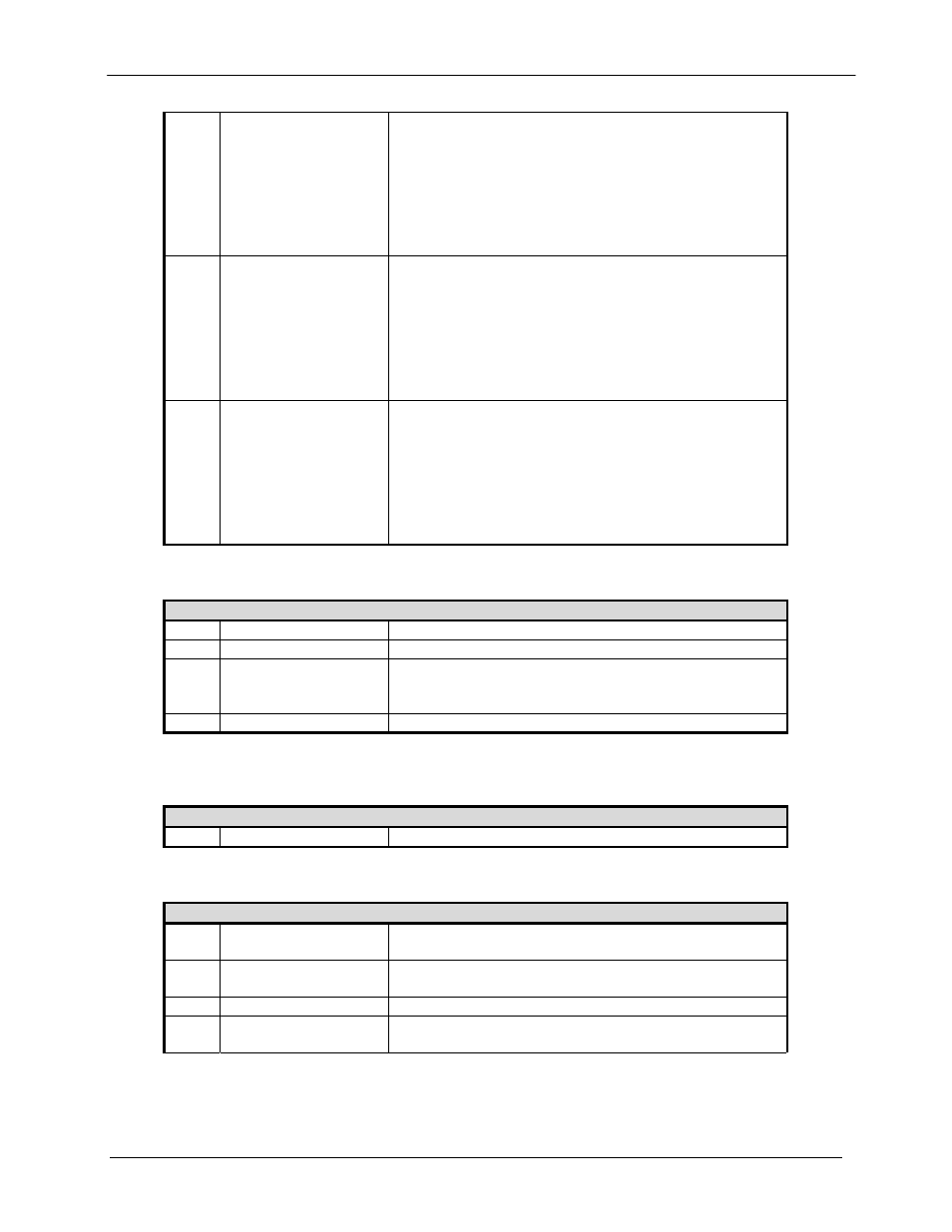
<1>
Common Alarm 2
Bit 0 = TERR FPGA Config, 1 = Fail
Bit 1 = CODEC FPGA Config, 1 = Fail
Bit 2 = CODEC Device Config, 1 = Fail
Bit 3 = TRANSEC Power Test, 1 = Fail
Bit 4 = +1.5 V Rx Alarm, 1 = Fail
Bit 5 = +1.5 V TX Alarm, 1 = Fail
Bit 6 = +3.3 V Alarm, 1 = Fail
Bit 7 = +20 V Alarm, 1 = Fail
<1>
Backward Alarms
Bit 0 = Backward Alarm 1 Transmitted
Bit 1 = Backward Alarm 2 Transmitted
Bit 2 = Backward Alarm 3 Transmitted
Bit 3 = Backward Alarm 4 Transmitted
Bits 4 & 5 = Spares
Bit 6 = IBS Prompt Alarm Transmitted
Bit 7 = IBS Service Alarm Transmitted
0 = No, 1 = Yes
<1>
Alarm 4
Bit 0 = LBST BUC DC Current Alarm, 1 = Fail
Bit 1 = LBST BUC DC Voltage Alarm, 1 = Fail
Bit 2 = Ethernet WAN Alarm, 1 = Fail
Bit 3 = LBST BUC PLL Alarm, 1 = Fail
Bit 4 = LBST BUC Over Temperature Alarm, 1 = Fail
Bit 5 = LBST BUC Summary Alarm, 1 = Fail
Bit 6 = LBST BUC Output Enable Alarm, 1 = Fail
Bit 7 = LBST BUC Communications Alarm, 1 = Fail
Opcode: <2451h>
Query a Modulator's Async Configuration
Query Response (4 Bytes)
<1>
ES Mode
0 = Normal, 1 = Enhanced
<1>
ES Type
0 = RS232, 1 = RS485
<1>
ES Baud Rate
0 =150, 1 = 300, 2 = 600, 3 = 1200, 4 = 2400, 5= 4800,
6 = 9600, 7 = 19200, 8 = 38400, 9 = 57600, 10 =
115200
<1>
ES Data Bits
0 = 7 bits, 1 = 8 bits
Opcode: <2600h>
Command a Modem's Control Mode (Deprecated on DMD20, listed for
backward compatibility only)
Command Data (1 Byte)
<1>
Modem control mode
0 = Front panel, 1 = Terminal, 2 = Computer
Opcode: <2601h>
Command a Modulator’s Configuration
Command Data (162 Bytes)
<1>
Network Spec
0 = Closed Net, 1 = IDR, 2 = IBS, 3 = D & I, 5 = DVB
SAT, 11 = MIL-188-165A, 16 = RFM, 17 = Ebem
<4>
Frequency
Selects the IF Frequency in Hz, IF Range = 50 MHz to
180 MHz, L-Band Range = 950 MHz to 2050 MHz
<2>
Strap Code
Binary value
<1>
Spectral Mask
0 = INTELSAT 0.35, 18 = MIL-188-165A, 20 = DVB
0.20, 25 = DVB 0.25, 35 = DVB 0.35