Addendum to section 14: real-time clock module, 1 rtc pins and control registers, 2 rtc operation overview – Maxim Integrated MAXQ Family Users Guide: MAXQ2010 Supplement User Manual
Page 63: Maxq family user’s guide: maxq2010 supplement
MAXQ Family User’s Guide:
MAXQ2010 Supplement
14-1
ADDENDUM TO SECTION 14: REAL-TIME CLOCK MODULE
The MAXQ2010 provides a real-time clock (RTC) that operates as described in the MAXQ Family User’s Guide.
Specific functions provided by the MAXQ2010 are as follows:
• Time-of-day alarm
• Subsecond interval alarm (8-bit width to support up to one-second intervals)
• Trim compensation function (controlled by RTRM register)
• Square-wave output for frequency generation and testing, controlled by the SQE and FT bits
14.1 RTC Pins and Control Registers
The associated pins and registers for this module are listed in Table 14-1 and Table 14-2.
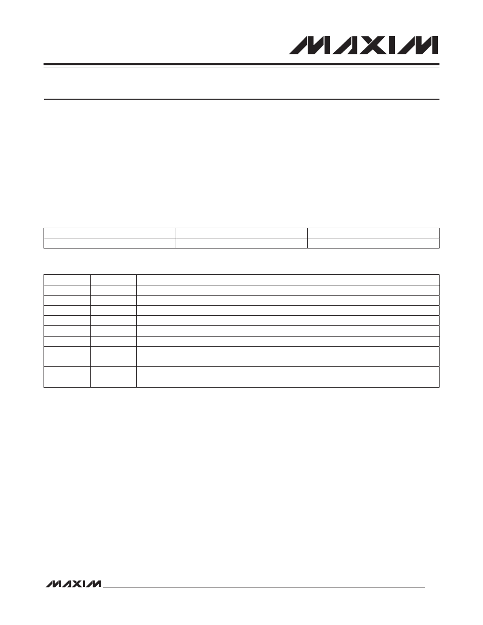
Table 14-1. RTC Output Pins
Table 14-2. RTC Control Registers
14.2 RTC Operation Overview
The binary RTC module keeps the time of day in absolute seconds with 1/256-second resolution. The 32-bit second
counter can count up to approximately 136 years and be translated to calendar format by application software. A time-
of-day alarm and independent subsecond alarm can cause an interrupt or wake the MAXQ2010 from stop mode. See
Figure 14-1.
The independent subsecond alarm runs from the same RTC and allows the user application to support interrupts with
a minimum interval of approximately 3.9ms with a maximum interval of one second. This creates an additional timer
that can be used to measure long periods of time without performance degradation.
Traditionally, long time periods have been measured using multiple interrupts from shorter interrupt intervals. Each
timer interrupt required servicing, with each accompanying interruption slowing system operation. By using the RTC
subsecond timer as a long-period timer, only one interrupt is needed, eliminating the performance hit associated with
using a shorter timer.
An internal crystal oscillator clocks the RTC using integrated 6pF load capacitors, and yields the best performance
when mated with a 32.768kHz crystal rated for a 6pF load. No external load capacitors are required.
Higher accuracy can be obtained by supplying an external clock source to the RTC.
SPI INTERFACE FUNCTION
PIN
MULTIPLEXED WITH GPIO
SQW: Square-Wave Output
61
P5.2
REGISTER
ADDRESS
FUNCTION
RTRM
M0[18h]
RTC Trim Register. Contains the 7-bit signed trim calibration value for the RTC.
RCNT
M0[19h]
RTC Control Register. Sets modes and alarm enables for the clock.
RTSS
M0[1Ah]
RTC Subsecond Counter Register. Contains the 1/256 subsecond count.
RTSH
M0[1Bh]
RTC Second Counter High Register. Contains the high-order byte of the 32-bit second count.
RTSL
M0[1Ch]
RTC Second Counter Low Register. Contains the low-order byte of the 32-bit second count.
RSSA
M0[1Dh]
RTC Subsecond Alarm Register. Contains the subsecond alarm reload value.
RASH
M0[1Eh]
RTC Time-of-Day Alarm High Register. Contains the high-order 8 bits of the time-of-day alarm
value.
RASL
M0[1Fh]
RTC Time-of-Day Alarm Low Register. Contains the low-order 16 bits of the time-of-day alarm
value.