11 lcd controller static drive example, 11 lcd controller static drive example -13, Maxq family user’s guide: maxq2010 supplement – Maxim Integrated MAXQ Family Users Guide: MAXQ2010 Supplement User Manual
Page 105
MAXQ Family User’s Guide:
MAXQ2010 Supplement
20-13
In x4 multiplexed mode, also known as 1/4 duty cycle mode, each segment pin can drive up to four LCD segments.
There are four common backplane signals, driven by COM0, COM1, COM2, and COM3. Each on segment is only
driven for 1/4 the frame period.
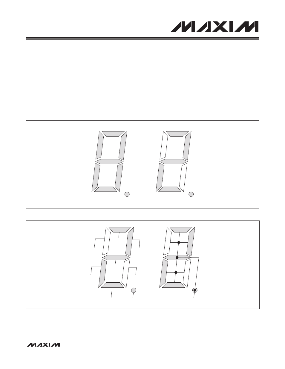
In each of the following examples, the LCD controller is driving a “2” to the display. This is a conventional 7-segment
display, and the “2” consists of on segments a, b, d, e, g, and DP as shown in Figure 20-4. The voltage waveforms
shown assume that V
ADJ
equals ground (R
ADJ
is set to 0I). The portions of the memory maps used apply to either
package type.
20.11 LCD Controller Static Drive Example
In this example, SEG0 to SEG7 are used to drive the LCD segments. The segments and common signals are con-
nected as shown in Figure 20-5.
Figure 20-4. Sample 7-Segment LCD Display
Figure 20-5. Static Drive Example Display Connection
a
b
c
d
f
g
e
DP
a
b
c
d
f
g
e
DP
COM0
SEG1
SEG2
SEG3
SEG5
SEG0
SEG7
SEG6
SEG4