Addendum to section 6: general-purpose i/o module, Maxq family user’s guide: maxq2010 supplement – Maxim Integrated MAXQ Family Users Guide: MAXQ2010 Supplement User Manual
Page 39
MAXQ Family User’s Guide:
MAXQ2010 Supplement
6-1
ADDENDUM TO SECTION 6: GENERAL-PURPOSE I/O MODULE
The MAXQ2010 provides up to 55 port pins for general-purpose I/O that are grouped into logical ports P0 to P6. Each
of these port pins has the following features:
• CMOS output drivers
• Schmitt trigger inputs
• Optional weak pullup to DVDD when operating in input mode
Many of the port pins on the MAXQ2010 are also multiplexed with special and alternate functions as listed below.
All these functions are disabled by default with the exception of the debug port interface pins, which are enabled by
default following any reset. The behavior of these functions breaks down into two overall categories.
• Special functions override the PD and PO settings for the port pin when they are enabled. Once the special func-
tion takes control, normal control of the port pin is lost until the special function completes its task or is disabled.
Examples of special functions include serial port 0 transmit and LCD segment drive.
• Alternate functions operate in parallel with the PD and PO settings for the port pin, and generally consist of input-
only functions such as external interrupts. When an alternate function is enabled for a port pin, the port pin’s output
state is still controlled in the usual manner.
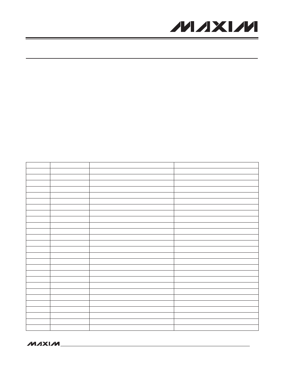
Table 6-1. Port Pin Special and Alternate Functions
PORT PIN
FUNCTION TYPE
FUNCTION
ENABLED WHEN
P0.0
Special Analog
LCD Segment SEG0
DPE = 1, PCF0 = 1, and EX0 = 0
P0.0
Alternate
External Interrupt 0
(EIE0.0) EX0 = 1
P0.1
Special Analog
LCD Segment SEG1
DPE = 1, PCF0 = 1, and EX1 = 0
P0.1
Alternate
External Interrupt 1
(EIE0.1) EX1 = 1
P0.2
Special Analog
LCD Segment SEG2
DPE = 1, PCF0 = 1, and EX2 = 0
P0.2
Alternate
External Interrupt 2
(EIE0.2) EX2 = 1
P0.3
Special Analog
LCD Segment SEG3
DPE = 1, PCF0 = 1, and EX3 = 0
P0.3
Alternate
External Interrupt 3
(EIE0.3) EX3 = 1
P0.4
Special Analog
LCD Segment SEG4
DPE = 1, PCF0 = 1, and EX4 = 0
P0.4
Alternate
External Interrupt 4
(EIE0.4) EX4 = 1
P0.5
Special Analog
LCD Segment SEG5
DPE = 1, PCF0 = 1, and EX5 = 0
P0.5
Alternate
External Interrupt 5
(EIE0.5) EX5 = 1
P0.6
Special Analog
LCD Segment SEG6
DPE = 1, PCF0 = 1, and EX6 = 0
P0.6
Alternate
External Interrupt 6
(EIE0.6) EX6 = 1
P0.7
Special Analog
LCD Segment SEG7
DPE = 1, PCF0 = 1, and EX7 = 0
P0.7
Alternate
External Interrupt 7
(EIE0.7) EX7 = 1
P1.0
Special Analog
LCD Segment SEG8
DPE = 1 and PCF1 = 1
P1.1
Special Analog
LCD Segment SEG9
DPE = 1 and PCF1 = 1
P1.2
Special Analog
LCD Segment SEG10
DPE = 1 and PCF1 = 1
P1.3
Special Analog
LCD Segment SEG11
DPE = 1 and PCF1 = 1
P1.4
Special Analog
LCD Segment SEG12
DPE = 1 and PCF1 = 1
P1.5
Special Analog
LCD Segment SEG13
DPE = 1 and PCF1 = 1
P1.6
Special Analog
LCD Segment SEG14
DPE = 1 and PCF1 = 1
P1.7
Special Analog
LCD Segment SEG15
DPE = 1 and PCF1 = 1
P2.0
Special Analog
LCD Segment SEG16
DPE = 1 and PCF2 = 1
P2.1
Special Analog
LCD Segment SEG17
DPE = 1 and PCF2 = 1
P2.2
Special Analog
LCD Segment SEG18
DPE = 1 and PCF2 = 1