2 external 32khz crystal oscillator circuit, 2 external 32khz crystal oscillator circuit -6, Figure 2-5. maxq2010 clock sources -6 – Maxim Integrated MAXQ Family Users Guide: MAXQ2010 Supplement User Manual
Page 18: Maxq family user’s guide: maxq2010 supplement
MAXQ Family User’s Guide:
MAXQ2010 Supplement
2-6
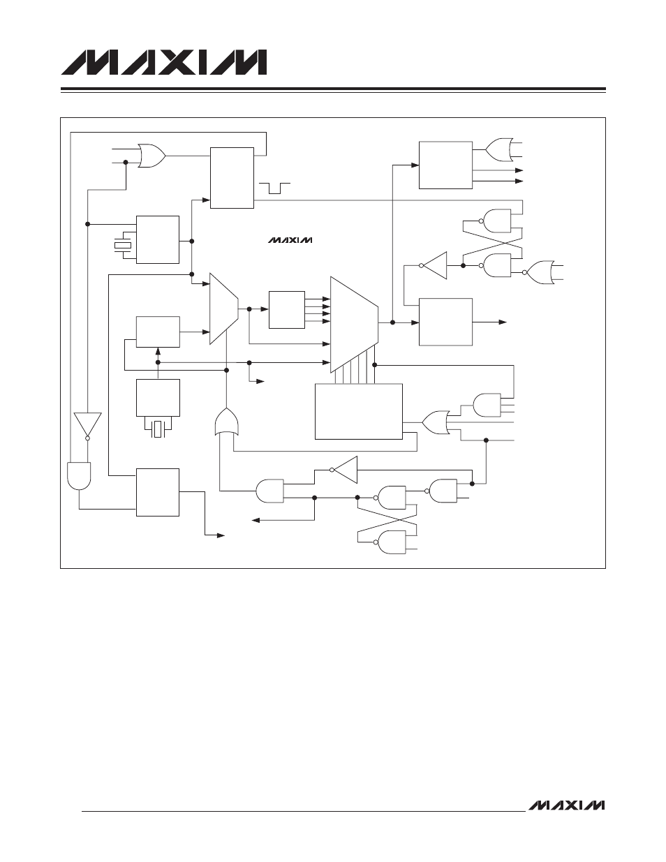
2.6.2 External 32kHz Crystal Oscillator Circuit
The 32kHz oscillator operates as described in Section 2.7: Clock Generation of the MAXQ Family User’s Guide. It can-
not be used directly as a system clock source, but instead works as an input to the FLL. It can also be used directly by
the LCD controller and RTC modules, regardless of the current system clock source selection. This clock can be gener-
ated by an internal 32kHz crystal oscillator, using an external crystal connected between the 32KIN and 32KOUT pins.
Setting X32D (PWCN.2) to 1 disables the 32kHz clock source completely. This should only be done when all the fol-
lowing conditions are true:
• Either the high-frequency oscillator is being used as the system clock source, or if the FLL is being used as the
system clock source, it is already enabled and locked.
• The 32kHz clock is not being used to drive either the RTC or the LCD controller.
If X32D = 0, the control bit X32KBYP (PWCN.5) can be used to switch between the internal oscillator and external
32kHz clock modes of operation.
Figure 2-5. MAXQ2010 Clock Sources
GLITCH-FREE
MUX
GLITCH-FREE
MUX
DIV
1
DIV
2
DIV
4
DIV
8
32kHz PMM1
CLOCK
DIVIDER
SELECTOR
WAKE-UP
TIMER, LCD
CONTROLLER
DEFAULT
FLL SELECT
WATCHDOG
TIMER
RESET DOG
RWT
RESET
POWER-ON
RESET
STOP
STOP
POWER-ON
RESET
SWB
INTERRUPT/SERIAL PORT
RESET
STOP
FLLSL
XDOG DONE
FLLMD
POWER-ON RESET
WATCHDOG RESET
CLOCK
GENERATION
SYSTEM CLOCK
ENABLE
WATCHDOG INTERRUPT
FLL
ENABLE
32kHz
CRYSTAL
CRYSTAL
MONITOR
ENABLE
INPUT
HF
CRYSTAL
CRYSTAL KLL
XDOG
STARTUP
TIMER
CLK INPUT
RESET
XDOG COUNT
XDOG DONE
MAXQ2010