1 i2c data read and write, 2 i2c address transmission, 2 i2c status register (i2cst, m3[01h]) – Maxim Integrated MAXQ Family Users Guide: MAXQ2010 Supplement User Manual
Page 125: C data read and write -2, C address transmission -2, C status register (i2cst, m3[01h]) -2, Maxq family user’s guide: maxq2010 supplement, C status register (i2cst, m3[01h])
MAXQ Family User’s Guide:
MAXQ2010 Supplement
22-2
22.1.1.1 I
2
C Data Read and Write
Data for I
2
C transfer is read and written to this location. The I
2
C transmit and receive buffers are internally stored sepa-
rately; however, both are accessed through this buffer.
22.1.1.2 I
2
C Address Transmission
When transmitting an I
2
C address, the address should be loaded into I2CBUF[6:0]. I2CBUF[7] is ignored and is not
part of the I
2
C address.
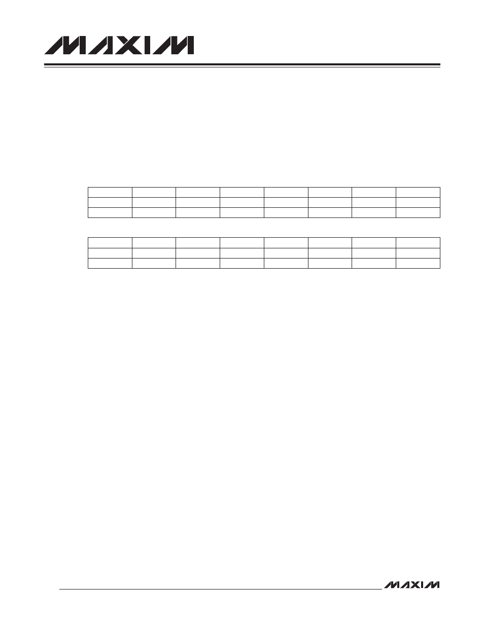
22.1.2 I
2
C Status Register (I2CST, M3[01h])
Bit 15: I
2
C Bus Busy (I2CBUS). This bit is set to 1 when a START/repeated START condition is detected and cleared
to 0 when the STOP condition is detected. This bit is reset to 0 on all forms of reset and when I2CEN = 0. This bit is
controlled by hardware and is read-only.
Bit 14: I
2
C Busy (I2CBUSY). This bit is used to indicate the current status of the I
2
C module. The I2CBUSY is set to 1
when the I
2
C controller is actively participating in a transaction or when it does not have control of the bus. This bit is
controlled by hardware and is read-only.
Bits 13:12: Reserved. Read returns 0.
Bit 11: I
2
C STOP Interrupt Flag (I2CSPI). This bit is set to 1 when a STOP condition (P) is detected. This bit must be
cleared to 0 by software once set. Setting this bit to 1 by software causes an interrupt if enabled.
Bit 10: I
2
C SCL Status (I2CSCL). This bit reflects the logic state of SCL signal. This bit is set to 1 when SCL is at a
logic-high (1), and cleared to 0 when SCL is at a logic-low (0). This bit is controlled by hardware and is read-only.
Bit 9: I
2
C Receiver Overrun Flag (I2CROI). This bit indicates a receive overrun when set to 1. This bit is set to 1 if
the receiver has already received two bytes since the last CPU read. This bit is cleared to 0 by software reading the
I2CBUF. Setting this bit to 1 by software causes an interrupt if enabled. Writing 0 to this bit does not clear the interrupt.
Bit 8: I
2
C General Call Interrupt Flag (I2CGCI). This bit is set to 1 when the general call is enabled (I2CGCEN = 1)
and the general call address is received. This bit must be cleared to 0 by software once set. Setting this bit to 1 by
software causes an interrupt if enabled.
Bit 7: I
2
C NACK Interrupt Flag (I2CNACKI). This bit is set to 1 if the I
2
C transmitter receives a NACK from the receiver.
Setting this bit to 1 by hardware causes an interrupt if enabled. This bit must be cleared to 0 by software once set. This
bit is set by hardware only.
Bit 6: I
2
C Arbitration Loss Flag (I2CALI). This bit is set to 1 when the I
2
C is configured as a master and loses in the
arbitration. When the master loses arbitration, the I2CMST bit is cleared to 0. Setting this bit to 1 by hardware causes
an interrupt if enabled. This bit must be cleared to 0 by software once set. This bit is set by hardware only.
Bit 5: I
2
C Slave Address Match Interrupt Flag (I2CAMI). This bit is set to 1 when the I
2
C controller receives an
address that matches the contents in its slave address register (I2CSLA) during the address stage. This bit must be
cleared to 0 by software once set. Setting this bit to 1 by software causes an interrupt if enabled.
Bit #
15
14
13
12
11
10
9
8
Name
I2CBUS
I2CBUSY
—
—
I2CSPI
I2CSCL
I2CROI
I2CGCI
Reset
0
0
0
0
0
0
0
0
Access
r
r
r
r
rw
r
rw
rw
Bit #
7
6
5
4
3
2
1
0
Name
I2CNACKI
I2CALI
I2CAMI
I2CTOI
I2CSTRI
I2CRXI
I2CTXI
I2CSRI
Reset
0
0
0
0
0
0
0
0
Access
rw
rw
rw
rw
rw
rw
rw
rw