6 clock generation, 1 external high-frequency oscillator circuit, 6 clock generation -5 – Maxim Integrated MAXQ Family Users Guide: MAXQ2010 Supplement User Manual
Page 17: 1 external high-frequency oscillator circuit -5, Maxq family user’s guide: maxq2010 supplement
MAXQ Family User’s Guide:
MAXQ2010 Supplement
2-5
2.6 Clock Generation
All functional modules in the MAXQ2010 are synchronized to a single system clock. This system clock can be gener-
ated from one of the following clock sources:
• External high-frequency clock
• Internal high-frequency oscillator using external crystal or resonator circuit
• External 32kHz clock
• Internal 32kHz oscillator using external crystal or resonator circuit
• 256x frequency-locked loop (FLL) using 32kHz clock as an input source
The MAXQ2010 does not support an external RC relaxation oscillator circuit, and the FLL takes the place of the ring
oscillator found in some other devices. The 32kHz crystal oscillator could also be used directly by the LCD controller
and the RTC, regardless of the currently selected system clock source.
The following registers and bits are used to control clock generation and selection. For more information, see the reg-
ister descriptions in this guide and in the MAXQ Family User’s Guide.
2.6.1 External High-Frequency Oscillator Circuit
The high-frequency oscillator operates as described in Section 2.7: Clock Generation of the MAXQ Family User’s
Guide. If used, the external crystal or resonator circuit for this oscillator should be connected between the HFXIN and
HFXOUT pins.
The high-frequency oscillator can be disabled by setting HFXD (PWCN.4) to 1; this is only allowed if the high-frequency
oscillator is not currently being used as the clock source (FLLMD and FLLSL must both equal 1). In this configuration,
an external clock can be used to directly drive HFXIN; refer to the IC data sheet for more details.
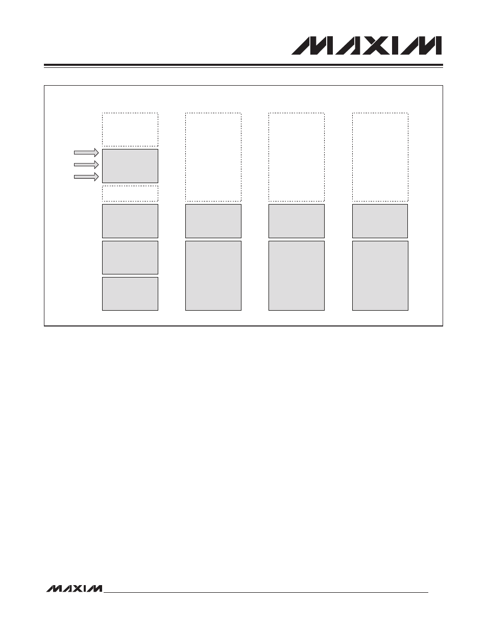
Figure 2-4. Memory Map When Executing from Data SRAM
2K x 16
UTILITY ROM
16K x 16
PROGRAM FLASH
(PAGE 0)
16K x 16
PROGRAM FLASH
(PAGE 1)
32K x 8
LOWER HALF
(PAGE 0) OF
PROGRAM FLASH
MEMORY
4K x 8
UTILITY ROM
32K x 8
UPPER HALF
(PAGE 1) OF
PROGRAM FLASH
MEMORY
4K x 8
UTILITY ROM
2K x 8
UTILITY ROM
FFFFh
FFFFh
8000h
A3FFh
A000h
87FFh
8000h
7FFFh
4000h
3FFFh
0000h
7FFFh
0000h
FFFFh
8000h
7FFFh
0000h
FFFFh
8000h
87FFh
8FFFh
8FFFh
7FFFh
0000h
1K x 16
DATA SRAM
PROGRAM
SPACE
DATA SPACE
(BYTE MODE, CDA0 = 0)
DATA SPACE
(BYTE MODE, CDA0 = 1)
DATA SPACE
(WORD MODE)
EXECUTING FROM
32K x 16
PROGRAM FLASH