Maxq family user’s guide: maxq2010 supplement – Maxim Integrated MAXQ Family Users Guide: MAXQ2010 Supplement User Manual
Page 115
MAXQ Family User’s Guide:
MAXQ2010 Supplement
21-4
Bit 5: Timer B Output Enable (TBOE). Setting this bit to 1 enables the clock output function on the TBA pin if C/TB =
0. Timer B rollovers do not cause interrupts. Clearing this bit to 0 allows the TBA pin to function as either a standard
port pin or a counter input for Timer B.
Bit 4: Down-Count Enable (DCEN). This bit, in conjunction with the TBB pin, controls the direction that Timer B
counts in 16-bit autoreload mode. Clearing this bit to 0 causes Timer B to count up only. Setting this bit to 1 enables
the up/down-counting mode (i.e., it causes Timer B to count up if the TBB pin is 1 and to count down if the TBB pin is
0). When Timer B PWM-output mode functionality is enabled along with up/down counting (DCEN = 1), the up/down
count control of Timer B is controlled internally based upon the count in relation to the register settings. In the compare
modes, the DCEN bit controls whether the timer counts up and resets (DCEN = 0), or counts up and down (DCEN = 1).
Bit 3: Timer B External Enable (EXENB). Setting this bit to 1 enables the capture/reload function on the TBB pin for a
negative transition (in up-counting mode). A reload results in TBnV being reset to 0000h. Clearing this bit to 0 causes
Timer B to ignore all external events on TBB pin. When operating in autoreload mode (CP/RLB = 0) with the PWM output
functionality enabled, enabling the TBB input function (EXENB = 1) allows PWM output negative transitions to set the
EXFB flag, however no reload occurs as a result of the external negative-edge detection.
Bit 2: Timer B Run Control (TRB). This bit enables Timer B operation when set to 1. Clearing this bit to 0 halts Timer
B operation and preserves the current count in TBnV.
Bit 1: Enable Timer B Interrupt (ETB). Setting this bit to 1 enables the interrupt from the Timer B TFB and EXFB flags
in TBnCN. In Timer B clock-output mode (TBOE = 1), the timer overflow flag (TFB) is still set on an overflow, however,
the TBOE = 1 condition prevents this flag from causing an interrupt when ETB = 1.
Bit 0: Capture/Reload Select (CP/RLB). This bit determines whether the capture or reload function is used for Timer
B. Timer B functions in an autoreload mode following each overflow/underflow. See the TFB bit description for overflow/
underflow condition. Setting this bit to 1 causes a Timer B capture to occur when a falling edge is detected on TBB if
EXENB is 1. Clearing this bit to 0 causes an autoreload to occur when Timer B overflow or a falling edge is detected on
TBB if EXENB is 1. It is not intended that the Timer B compare functionality should be used when operating in capture
mode.
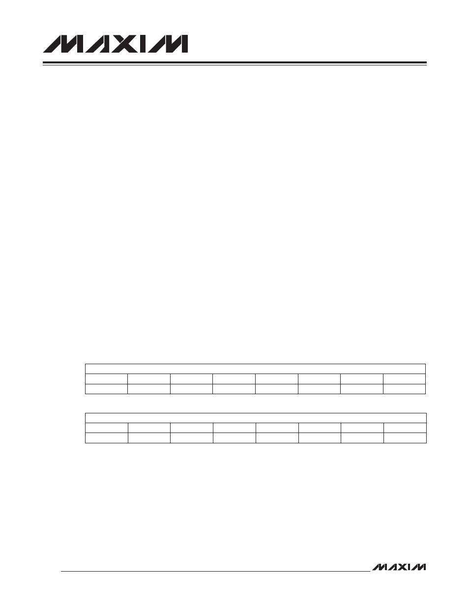
21.1.4 Timer B Timer/Counter 0/1/2 Value Register (TB0V, TB1V, TB2V; M4[09h],
M4[0Bh], M4[0Dh])
Bits 15:0: Timer B Value Register. This register is used to load and read the 16-bit Timer B value.
Bit #
15
14
13
12
11
10
9
8
Name
TBnV
Reset
0
0
0
0
0
0
0
0
Access
rw
rw
rw
rw
rw
rw
rw
rw
Bit #
7
6
5
4
3
2
1
0
Name
TBnV
Reset
0
0
0
0
0
0
0
0
Access
rw
rw
rw
rw
rw
rw
rw
rw