Maxq family user’s guide: maxq2010 supplement – Maxim Integrated MAXQ Family Users Guide: MAXQ2010 Supplement User Manual
Page 114
MAXQ Family User’s Guide:
MAXQ2010 Supplement
21-3
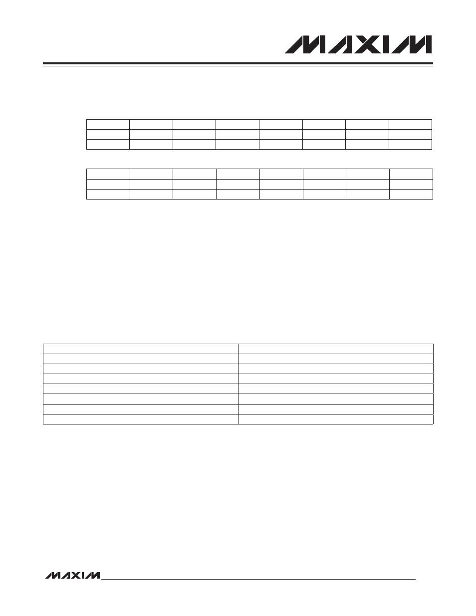
21.1.3 Timer B Timer/Counter 0/1/2 Control Register (TB0CN, TB1CN, TB2CN; M4[08h],
M4[0Ah], M4[0Ch])
Bit 15: Counter/Timer Select (C/TB). This bit determines whether Timer B functions as a timer or counter. Setting this
bit to 1 causes Timer B to count negative transitions on the TBA pin. Clearing this bit to 0 causes Timer B to function
as a timer. The speed of Timer B is determined by the TBPS[2:0] bits of TBnCN.
Bits 14:13: Reserved. Read returns zero.
Bits 12:11: TBB Pin Output Reset/Set Mode Bits (TBCS, TBCR). These mode bits define whether the PWM mode
output function is enabled on the TBB pin, the initial output starting state, and what compare mode output function is
in effect. Note that the TBB pin still has certain input functionality when the PWM output function is enabled.
Bits 10:8: Timer B Clock Prescaler Bits (TBPS[2:0]). These bits select the clock prescaler applied to the system
clock input to Timer B. The TBPS[2:0] bits should be configured by the user when the timer is stopped (TRB = 0).
While hardware does not prevent changing the TBPS[2:0] bits when the timer is running, the resultant behavior is
indeterministic.
Timer B Clock = System Clock/2
(2 x TBPS[2:0])
Bit 7: Timer B Overflow Flag (TFB). This bit is set when Timer B overflows from TBnR or the count is equal to 0000h
in down-count mode. It must be cleared by software.
Bit 6: External Timer B Trigger Flag (EXFB). When configured as a Timer (C/TB = 0), a negative transition on the
TBB pin causes this flag to be set if (CP/RLB = EXENB = 1) or (CP/RLB = DCEN = 0 and EXENB = 1) or (CP/RLB = 0
and EXENB = 1 and TBCS:TBCR<>00b). When configured in any of these ways, this flag can be set independent of
the state of the TRB bit (e.g., EXFB can still be set on detection of a negative edge when TRB = 0).
When CP/RLB = 0 and DCEN = 1 and TBCS:TBCR = 00b, EXFB toggles whenever Timer B underflows or overflows.
Overflow/underflow condition is the same as described in TFB bit description. In this mode, EXFB can be used as the
17th timer bit and does not cause an interrupt. If set by a negative transition, this flag must be cleared by software.
Setting this bit to 1 forces a timer interrupt if enabled.
Bit #
15
14
13
12
11
10
9
8
Name
C/TB
—
—
TBCS
TBCR
TBPS2
TBPS1
TBPS0
Reset
0
0
0
0
0
0
0
0
Access
rw
rw
rw
rw
rw
rw
rw
rw
Bit #
7
6
5
4
3
2
1
0
Name
TFB
EXFB
TBOE
DCEN
EXENB
TRB
ETB
CP/RLB
Reset
0
0
0
0
0
0
0
0
Access
rw
rw
rw
rw
rw
rw
rw
rw
TBPS[2:0]
TIMER B INPUT CLOCK
000
Sysclk/1
001
Sysclk/4
010
Sysclk/16
011
Sysclk/64
100
Sysclk/256
101
Sysclk/1024
11x
Sysclk/1