12 lcd controller 1/2 duty cycle drive example, 13 lcd controller 1/3 duty cycle drive example, Maxq family user’s guide: maxq2010 supplement – Maxim Integrated MAXQ Family Users Guide: MAXQ2010 Supplement User Manual
Page 107
MAXQ Family User’s Guide:
MAXQ2010 Supplement
20-15
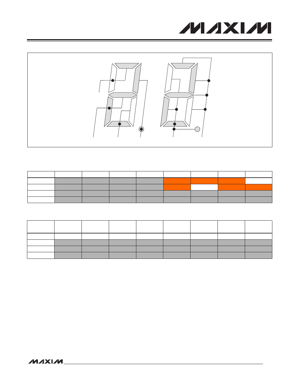
20.12 LCD Controller 1/2 Duty Cycle Drive Example
In this example, SEG0 to SEG3 are used to drive the LCD segments. The segments and common signals are con-
nected as shown in Figure 20-7.
According to the 1/2 duty drive memory map table, a value of 0DEh should be written to the LCD0 register as shown
in Table 20-10.
20.13 LCD Controller 1/3 Duty Cycle Drive Example
In this example, SEG0 to SEG2 are used to drive the LCD segments. The segments and common signals are con-
nected as shown in Figure 20-9 .
According to the 1/3 duty drive memory map table, LCD0 should be set to 071h and LCD1 should be set to 05h as
shown in Table 20-12.
Figure 20-7. 1/2 Duty Drive Example Display Connection
Table 20-9. 1/2 Duty Drive Example Common Signal Selection
Table 20-10. 1/2 Duty Drive Example Register Content
SEG3
SEG2
SEG1
SEG0
COM1
COM0
SEG7
SEG6
SEG5
SEG4
SEG3
SEG2
SEG1
SEG0
COM0
On
On
On
Off
COM1
On
Off
On
On
COM2
COM3
BIT 7
COM1
BIT 6
COM0
BIT 5
COM1
BIT 4
COM0
BIT 3
COM1
BIT 2
COM0
BIT 1
COM1
BIT 0
COM0
LCD0
1
1
0
1
1
1
1
0
LCD1
LCD2
LCD3