Maxq family user’s guide: maxq2010 supplement – Maxim Integrated MAXQ Family Users Guide: MAXQ2010 Supplement User Manual
Page 118
MAXQ Family User’s Guide:
MAXQ2010 Supplement
21-7
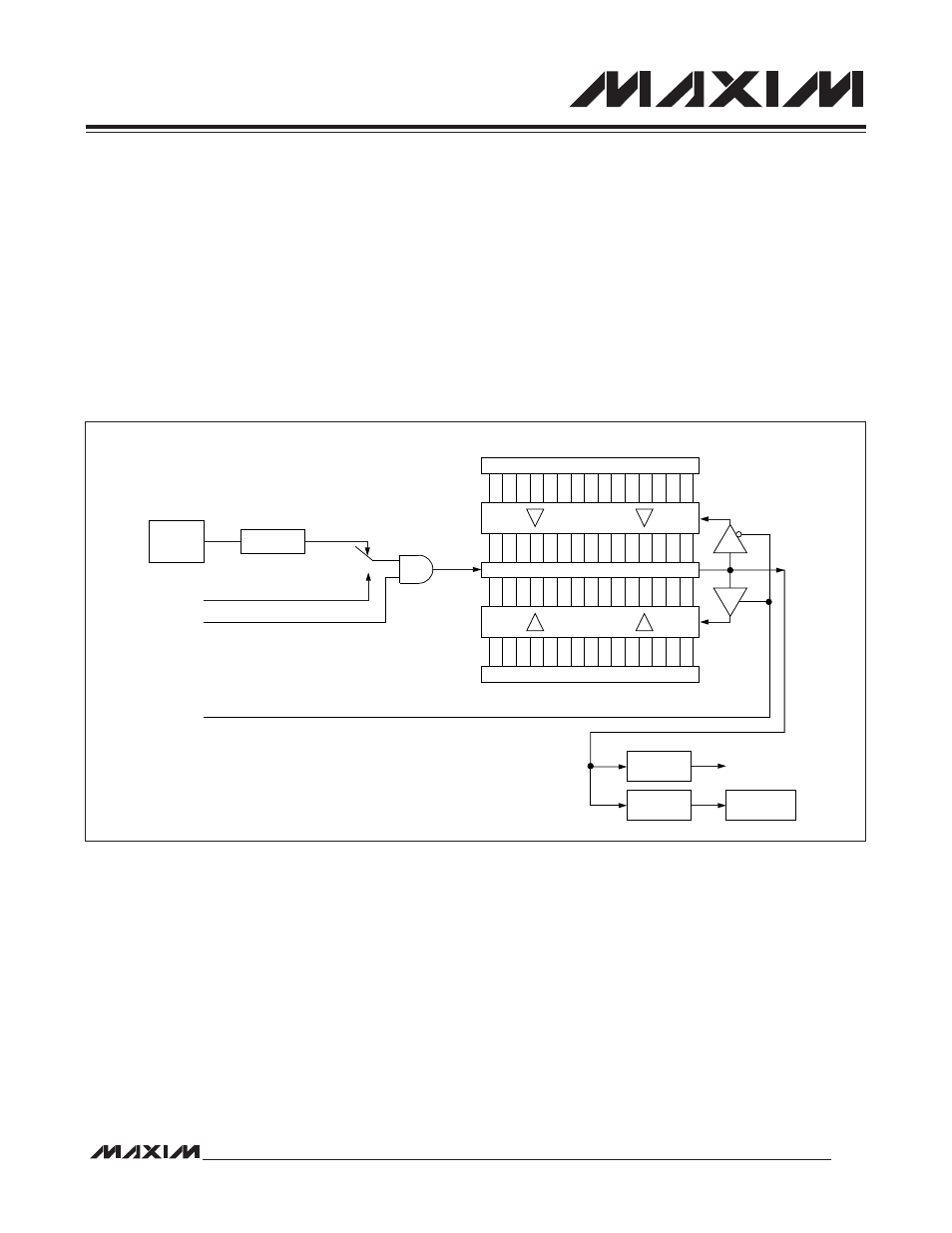
21.2.3 Timer B 16-Bit Up/Down Count with Autoreload Mode
The 16-bit up/down-count autoreload mode is enabled by clearing the capture/reload bit CP/RLB of the control reg-
ister (TBnCN.0) to 0 and setting the down-count enable bit, DCEN (TBnCN.4), to 1. This mode is illustrated in Figure
21-3. When DCEN is set to 1, Timer B counts up from 0000h or down from the value contained in the TBnR register as
controlled by the state of the TBB pin. When the TBB pin is 1, the timer counts up, and counts down when the pin is 0.
When DCEN is 0, Timer B can only count up.
When counting up and a match occurs between the value in the TBnV register and value in the TBnR register, the value
of 0000h is loaded into the TBnV register. When counting down and the value in the TBnV register reaches 0000h, the
value in the TBnR register is loaded into the TBnV register and downward counting continues.
Note that in this mode of operation, the overflow/underflow output of the timer is provided to an edge-detection circuit
as well as to the TBF bit of the control register (TBnCN.7). This edge-detection circuit toggles the EXFB bit (TBnCN.6)
on every overflow or underflow. Therefore, the EXFB bit behaves as a 17th bit of the counter, and can be used as such.
Figure 21-3. Timer B 16-Bit Up/Down Count with Autoreload Mode Block Diagram
TIMER B INTERRUPT
15
0
15
0
(DOWN-COUNTING RELOAD VALUE)
(UP-COUNTING RELOAD VALUE)
COUNT DIRECTION (1 = UP, 0 = DOWN)
TBB PIN
TBnR
TBnV
0000h
0
1
TBA PIN
TRB = TBnCN.2
SYSTEM
CLOCK
C/TB = TBnCN.15
TFB = TBnCN.7
EXFB = TBnCN.6
RISE/FALL
EDGE
/CLK
2
(2 x TBPS[2:0])
TBPS[2:0] = TBnCN[10:8]