3 frequency-locked loop (fll), 3 frequency-locked loop (fll) -7, Maxq family user’s guide: maxq2010 supplement – Maxim Integrated MAXQ Family Users Guide: MAXQ2010 Supplement User Manual
Page 19
MAXQ Family User’s Guide:
MAXQ2010 Supplement
2-7
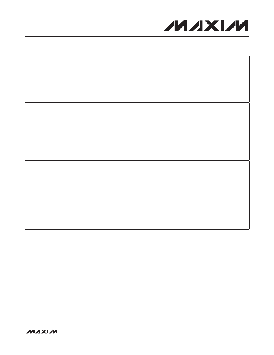
Table 2-1. System Clock Generation and Control Registers
2.6.3 Frequency-Locked Loop (FLL)
The MAXQ2010 contains an FLL circuit that provides an optional, low-cost method of generating a high-frequency
system clock. The FLL uses the 32kHz clock as an input, multiplying its frequency by 256 to generate a clock output of
approximately 8.4MHz (refer to the IC data sheet for details). This clock output can be used as a system clock source.
On power-on reset, the FLL is automatically enabled as the system clock source while the high-frequency oscillator
warms up. Once the warmup count for the high-frequency oscillator has completed, the clock source switches to the
high-frequency oscillator automatically. If no external crystal or resonator circuit is provided at HFXIN, the switchover
never occurs, and the clock runs from the FLL indefinitely.
To select the FLL as the system clock source permanently, the FLLSL bit (CKCN.6) must be set to 1. Setting this bit
immediately switches over the system clock source to the FLL. The FLLMD (CKCN.5) bit indicates the current system
clock source. If the FLL is currently providing the system clock, FLLMD = 1; otherwise, FLLMD = 0.
Since the FLLSL bit is cleared by power-on reset only, if this bit is set before entering stop mode, the FLL is still used
as the system clock source when stop mode is exited. In this case, a four-cycle warmup delay is required when exiting
stop mode before execution resumes using the FLL as the system clock source.
REGISTER
ADDRESS
BIT(S)
FUNCTION
CKCN
M8[0Eh]
[2:0]—PMME,
CD[1:0]
000: System clock = high-frequency clock divided by 1.
001: System clock = high-frequency clock divided by 2.
010: System clock = high-frequency clock divided by 4.
011: System clock = high-frequency clock divided by 8.
1xx: System clock = high-frequency clock/256.
CKCN
M8[0Eh]
5—FLLMD
0: System clock is being provided by an external source.
1: System clock is being provided by the FLL.
CKCN
M8[0Eh]
6—FLLSL
0: Selects an external source for system clock generation.
1: Selects the FLL for system clock generation.
PWCN
M0[0Fh]
0—FLLEN
0: Disables the FLL (unless it is providing the system clock).
1: Enables the FLL and locks it to the 32kHz input.
PWCN
M0[0Fh]
1—FLOCK
0: Indicates the FLL is disabled or in the process of locking.
1: Indicates the FLL is locked to the 32kHz input.
PWCN
M0[0Fh]
2—X32D
0: 32kHz clock or oscillator operates normally (default).
1: Disables the 32kHz source completely (except in stop).
PWCN
M0[0Fh]
3—X32KRDY
0: Indicates the 32kHz oscillator is still warming up.
1: Indicates the 32kHz oscillator is ready for use.
PWCN
M0[0Fh]
4—HFXD
0: High-frequency oscillator operates normally (default).
1: Disables the high-frequency oscillator, allowing an external clock to be
provided at HFXIN.
PWCN
M0[0Fh]
5—X32KBYP
0: 32kHz clock is provided by internal oscillator (default).
1: Disables the 32kHz oscillator, allowing an external clock to be provided at
32KIN.
PWCN
M0[0Fh]
[9:8]—X32KMD
00: 32kHz oscillator operates in noise immune mode.
01: 32kHz oscillator operates in quiet mode.
10: 32kHz oscillator operates in noise immune mode normally and in quiet mode
during stop mode. (Note: This setting should not be used on devices of rev
B3 or earlier; refer to the device errata for more details.)
11: 32kHz oscillator operates in quiet mode normally and in noise immune mode
during stop mode.