Figure 2-7. external reset timing -11, Table 2-3. system power-management registers -11, Maxq family user’s guide: maxq2010 supplement – Maxim Integrated MAXQ Family Users Guide: MAXQ2010 Supplement User Manual
Page 23: Table 2-3. system power-management registers
MAXQ Family User’s Guide:
MAXQ2010 Supplement
2-11
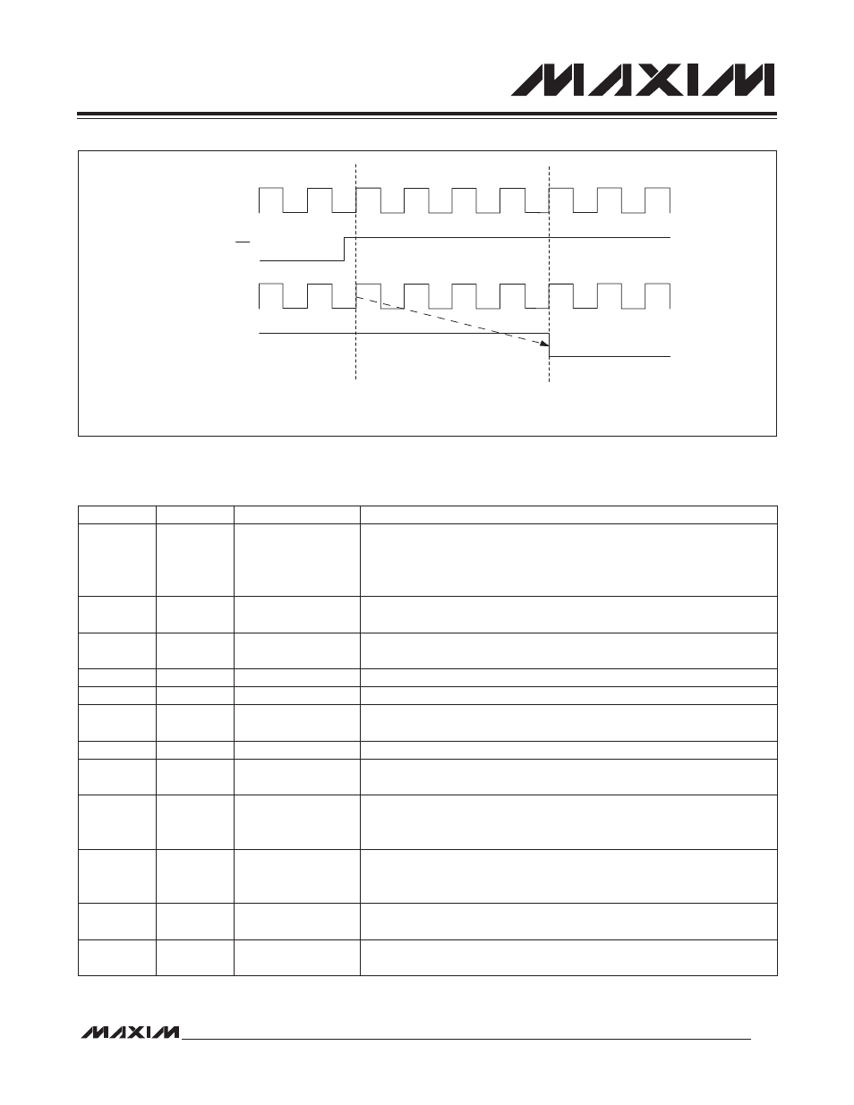
Figure 2-7. External Reset Timing
Table 2-3. System Power-Management Registers
CLOCK
RST
RESET SAMPLING
INTERNAL RESET
FIRST
INSTRUCTION
FETCH
REGISTER
ADDRESS
BIT
FUNCTION
CKCN
M8[0Eh]
[1:0]—CD[1:0]
00: System clock = high-frequency clock divided by 1.
01: System clock = high-frequency clock divided by 2.
10: System clock = high-frequency clock divided by 4.
11: System clock = high-frequency clock divided by 8.
CKCN
M8[0Eh]
2—PMME
0: System clock is determined by the settings of CD[1:0].
1: System clock = high-frequency clock divided by 256.
CKCN
M8[0Eh]
3—SWB
When set to 1, enables automatic switchback from PMM (divide-by-256
mode) to normal clock-divide mode under certain conditions.
CKCN
M8[0Eh]
4—STOP
When set to 1, causes the processor to enter stop mode.
PWCN
M0[0Fh]
0—FLLEN
When set to 1, enables the FLL and causes it to lock to the 32kHz input.
PWCN
M0[0Fh]
1—FLOCK
0: FLL is disabled or warming up.
1: FLL is enabled and locked to the 32kHz input.
PWCN
M0[0Fh]
2—X32D
When set to 1, disables the 32kHz clock source.
PWCN
M0[0Fh]
3—X32KRDY
Read-only status bit; when 1, indicates that the 32kHz clock is ready for
use.
PWCN
M0[0Fh]
4—HFXD
0: Enables the high-frequency oscillator.
1: Disables the high-frequency oscillator, allowing an external clock to be
provided at HFXIN.
PWCN
M0[0Fh]
5—X32KBYP
0: Enables the internal 32kHz oscillator.
1: Disables the internal 32kHz oscillator, allowing an external clock to be
provided at 32KIN.
PWCN
M0[0Fh]
6—REGEN
0: Internal regulator is shut down during stop mode.
1: Internal regulator remains powered on during stop mode.
PWCN
M0[0Fh]
7—BOD
0: Brownout detection remains enabled during stop mode.
1: Brownout detection is enabled during stop mode.