6 i2c timeout register (i2cto, m3[0eh]), 7 i2c slave address register (i2csla, m3[0fh]), C timeout register (i2cto, m3[0eh]) -6 – Maxim Integrated MAXQ Family Users Guide: MAXQ2010 Supplement User Manual
Page 129: C slave address register (i2csla, m3[0fh]) -6, Maxq family user’s guide: maxq2010 supplement, C timeout register (i2cto, m3[0eh]), C slave address register (i2csla, m3[0fh])
MAXQ Family User’s Guide:
MAXQ2010 Supplement
22-6
Bits 7:0: I
2
C Clock Low (I2CCKL[7:0]). These bits define the I
2
C SCL low period in number of system clock, with bit
7 as the most significant bit. The duration of SCL low time is calculated using the following equation:
I
2
C Low Time Period = System Clock x (I2CCKL[7:0] + 1)
When operating in master mode, I2CCKL must be set to a minimum value of 4 to ensure proper operation. Any value
less than 4 is set to 4.
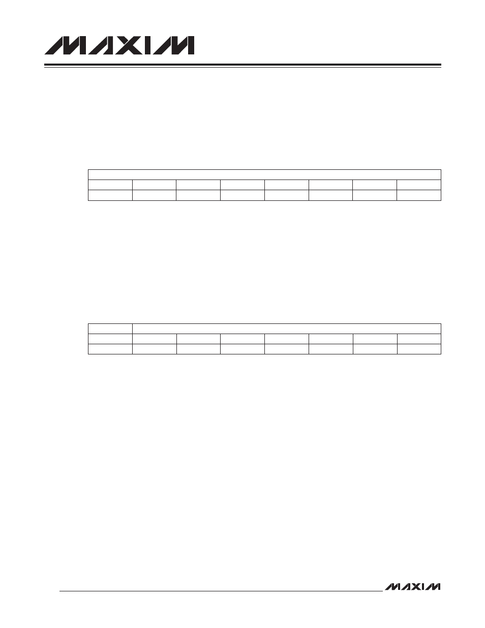
22.1.6 I
2
C Timeout Register (I2CTO, M3[0Eh])
Bits 7:0: I
2
C Timeout Register. This register is used only in master mode. This register determines the number of the
I
2
C bit period (SCL high + SCL low) the I
2
C master waits for SCL to go high. The timeout timer resets to 0 and starts
to count after the I2CSTART bit is set, or every time the SCL goes low. When cleared to 00h, the timeout function is
disabled and the I
2
C waits for SCL to go high indefinitely during a transmission. When set to any other values, the I
2
C
waits until the timeout expires and sets the I2CTOI flag.
I
2
C Timeout = I
2
C Bit Rate x (I2CTO[7:0] + 1)
Note that these bits have no effect when the I
2
C module is operating in slave mode (I2CMST = 0). When operating in
slave mode, SCL is controlled by an external master.
22.1.7 I
2
C Slave Address Register (I2CSLA, M3[0Fh])
Bit 7: Reserved. Read returns zero.
Bits 6:0: I
2
C Slave Address Register. These address bits contain the address of the I
2
C device. When a match to
this address is detected, the I
2
C controller automatically acknowledges the transmitter with the I2CACK bit value if
the I
2
C module is enabled (I2CEN = 1). The I2CAMI flag is set to 1 and the I2CMST bit is cleared to 0. An interrupt is
generated to the CPU if enabled.
Bit #
7
6
5
4
3
2
1
0
Name
I2CTO
Reset
0
0
0
0
0
0
0
0
Access
rw
rw
rw
rw
rw
rw
rw
rw
Bit #
7
6
5
4
3
2
1
0
Name
—
I2CSLA
Reset
0
0
0
0
0
0
0
0
Access
r
rw
rw
rw
rw
rw
rw
rw