Normal – KEYENCE LS-7000 User Manual
Page 87
4-35
Chapter 4 Function Settings
4
Timing Chart
The following table lists timing charts for respective measuring modes.
RUN mode
Timing chart name
Reference page
4-35
4-36
4-37
4-38
4-39
4-40
Normal
Peak Hold/Bottom Hold/
Peak-to-peak Hold/Average Hold
Auto Peak Hold/Auto Bottom Hold/
Auto Peak-to-peak Hold
Sample Hold 1
Sample Hold 2
Self-timing Hold
Normal
Peak Hold
Auto Peak Hold
Sample Hold 1
Sample Hold 2
Self-timing Hold
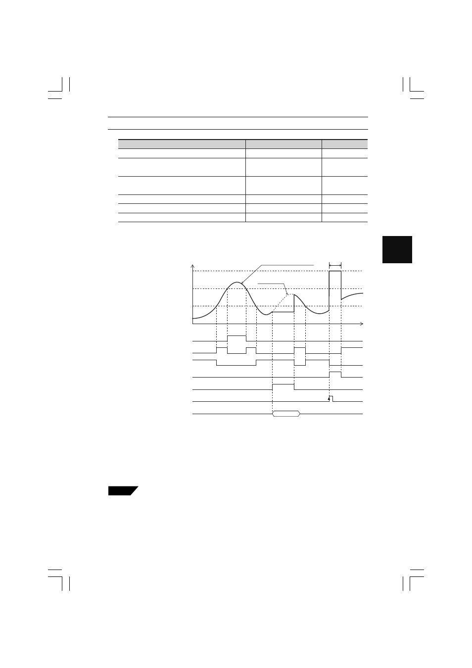
■ Normal
The value is continuously measured, displayed, and output in normal mode.
Measured value in normal mode
Internal measured value
ON
OFF
HI output
t
Waiting for judgment
(---------- displayed)
HI set value
Measured value
LO set value
ON
OFF
GO output
ON
OFF
LO output
ON
OFF
Judgment awaiting output
(Comparator waiting output)
ON
OFF
Timing input
ON
OFF
RESET input
ON
OFF
RS-232C output
Measured value
RESET processing
• In addition to the above output signals, HH output and LL output are available though they are omitted from
the above chart.
• In the above chart, the ON status of each output means that NPN open collector output is ON, provided
that it is normally open type. If it is normally closed type, the signal will be inverted.
• The ON status of each input means that the input is short-circuited to the COM terminal.
• RS-232C output is ON in synchronization with timing input if the D-SEND item as an environment setting is
set to S1 or S2 only. Refer to Data Transmission Mode on page 5-9 for environment settings in detail.
• For strobe output in detail, refer to Strobe Output Time on page 4-48.
• For BCD output in detail, refer to BCD Output on pages 6-9 and 6-13.
Tips
• If RESET input is ON while timing input is ON, awaiting the result of meas-
urement, the monitor will display the result waiting status “---.-----” until the
timing input is turned OFF.
• Comparator waiting output can be OFF-delayed. Refer to OFF-delay Time
on page 4-49 for the details of OFF-delays.
• Timing input and reset input can be sent by RS-232C control. Refer to page
7-8 for details.