About this manual, Definition of terms, Page configuration and symbols – KEYENCE LS-7000 User Manual
Page 7: This manual uses the following terms
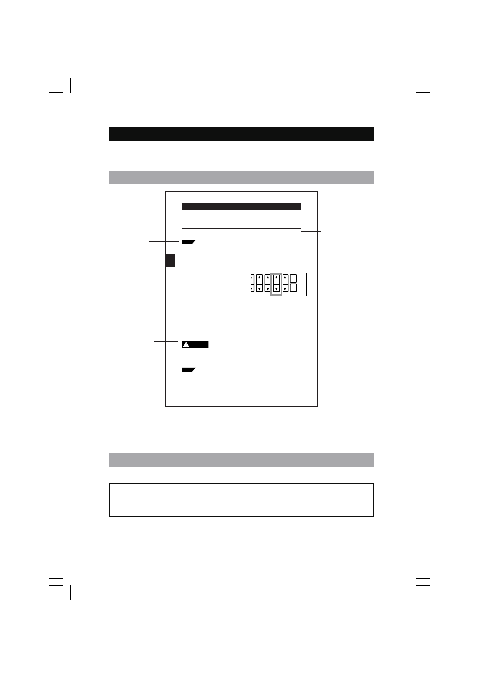
About this Manual
The following section provides information on the configuration of each page of this manual
along with symbols and terms used in this manual.
Page Configuration and Symbols
Tips: Describes
information that will
deepen the user’s
comprehension of
the manual along
with other useful
information.
Caution: Indicates
information that, if
not heeded, could
result in relatively
serious or minor
injury, damage to
the LS-7000 Series,
or faulty operation.
Note: Describes
items that need the
user’s attention in
order to prevent
mistakes in the
operation of the
LS-7000 Series.
3-10
Chapter 3 Operation Control
3
Automatic Zero Function
The automatic zero function sets measuring values to zero (0.00000) instantly. This func-
tion is convenient for zero-point calibration for a variety of target. Furthermore,
master calibration is possible by using this function in combination with the offset function.
Note:
This function will not be available while the controller is awaiting the result of
measurement, during which the LCD monitor will display “– – –. – – – –.”)
The automatic zero value will not be lost after the LS-7500 Series is turned
off. The automatic zero value for each program will be stored.
Automatic zero settings are made through the following functional components.
• Control panel
• External terminal
• RS-232C interface
Tips
■ Control Panel
If a single measuring value is displayed, an
automatic zero setting will be made for the
corresponding OUT number only.
If both measuring values are displayed, an
automatic zero setting will be made for the
selected OUT number on the screen.
1
Press the [ZERO] key once. Automatic
zero will be set.
To cancel the setting, press the [ZERO]
key again.
■ External I/O Terminal
Automatic zero will be set by short-circuiting the I/O, ZERO, and COM terminals on the
rear panel of the controller together.
Refer to Section 7 I/O Terminals on page 7-1 for details.
Master Calibration with Offset Function (Automatic Offset Function)
Set the size of a master workpiece to an offset value and make an automatic
zero setting while measuring the master workpiece. Then the size of the
master workpiece will be displayed as an offset value. Refer to 3-3 Measure-
ment of Outer Diameter and Width (with Two Measuring Heads) on page 3-4
for an application example.
Refer to Offset on page 5-43 for the offset function in detail.
Tips
• Do not look at the LED light source for a long time.
The LED used as the light source is classified into class 1
according to IEC60825-1 standards. Basically the light beam of
the LED is safe, but do not look at the LED for a long time
CAUTION
AREA
DISP
HOLD
ZERO
❈ The above page sample is for your reference only. It does not coincide with any of
the actual pages of this manual.
v
Term
Description
LS-7000 Series
Refers to the LS-7001 controller and the measuring head as a set.
Controller
Refers to the LS-7001 controller.
Measuring head
Refers to the LS-7010/LS-7030/LS-7070 measuring head.
Definition of Terms
This manual uses the following terms.