3 replacing the tam board, Replacing the tam board, Ab 5.3 replacing the tam board – Kontron TIGH2U Carrier Grade Server User Manual
Page 83
Kontron Carrier Grade Server TIGH2U
December 2009
Product Guide, rev.1.2
83
Server Component Replacements—TIGH2U Server
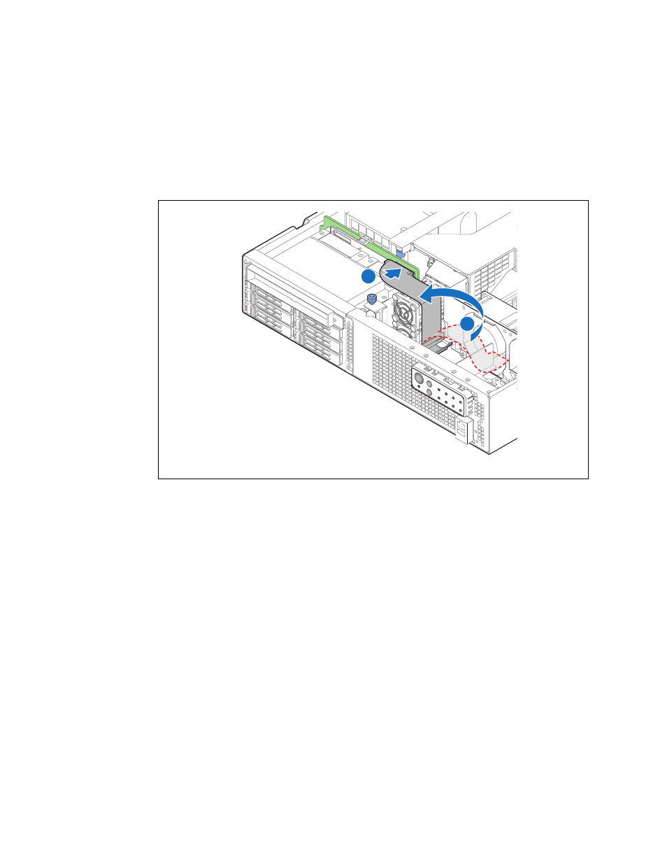
5. Lay the flex cable over the PCI fan assembly. (
, “A”)
6. Connect the flex cable to connector J5A1 on the SAS backplane board. (“B”)
7. Install the flex cable support bracket.
8. If this is the last task you are performing, replace the chassis top cover. Reconnect all the external
devices and plug in the power cord(s).
Figure 64.
Connecting the Flex Cable to the Backplane Board
TS000432
A
B
5.3
Replacing the TAM Board
The Telco Alarms Manager (TAM) board provides front panel LEDs, power controls, and a cable to
relay alarm information to the back of the system.
To replace the TAM board, the following components must be removed:
• Chassis top cover
• Processor air duct
• All cables connected to on the TAM board
Caution:
Before replacing any of the boards or components in the TIGH2U Server, you must first
take the server out of service, turn off all peripheral devices connected to the system,
turn off the system by pressing the power button, and unplug the power cord(s) from
the system or wall outlet.
When handling the TAM board, observe normal safety and ESD precautions. (See
Appendix A, “Safety Information”
for more information.)