1 cpu 1 and memory cooling area, 2 cpu 2 and chipset cooling area, 3 pci cooling area – Kontron TIGH2U Carrier Grade Server User Manual
Page 23: 4 hard disk drive and power supply cooling, 5 fan speed control
Kontron Carrier Grade Server TIGH2U
December 2009
Product Guide, rev.1.2
23
Features—TIGH2U Server
2.11.1
CPU 1 and Memory Cooling Area
One of the system’s large fans provides cooling for domain 1, outlined in blue in
facilitates the flow of air through the front bezel over the SFP, through the fan, and over the server
board, CPU 1, memory, and ultimately out through the rear of the chassis.
2.11.2
CPU 2 and Chipset Cooling Area
One of the system’s large fans provides cooling for domain 2, outlined in green in
. This fan
facilitates the flow of air through the front bezel over the SFP, through the fan, and over the server
board, CPU 2, chipset and any low-profile PCIe add-in cards, and ultimately out through the rear of
the chassis.
2.11.3
PCI Cooling Area
The two 40 Ч 40 Ч 56 mm dual-rotor fans (A in
) facilitate the flow of air through the front
bezel, through the fans, over the server board and any full-length PCI-X or PCIe add-in cards, and
ultimately out through the rear of the chassis.
2.11.4
Hard Disk Drive and Power Supply Cooling
Fans that are integrated into the PSUs provide the airflow to cool the hard disk drives. The airflow is
adequate even with a single PSU installed as long as a filler panel is installed in the other PSU slot.
2.11.5
Fan Speed Control
The server board contains Pulse Width Modulation (PWM) circuits, which control the 12 VDC fan
voltage to provide quiet operation when system ambient temperature is low and there are no fan
failures. There is one PWM circuit for each cooling domain, resulting in one PWM being connected to
each of the two 80 × 38 mm fans and the other PWM connected to the two dual-rotor 56 × 40 mm
fans. Based on the ambient temperature, monitored by the front panel sensor, the fan speeds (PWM
duty cycle) are set per
.
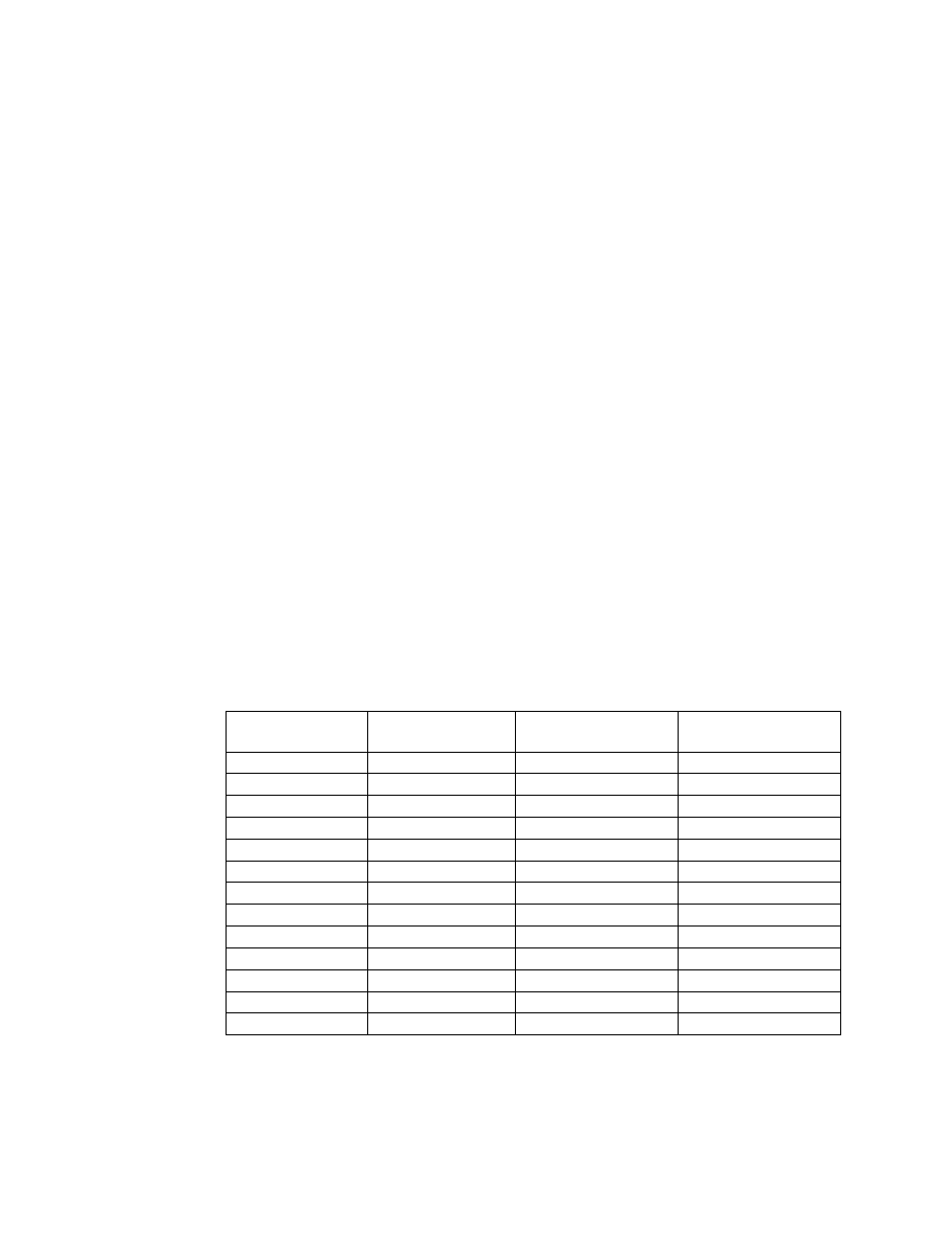
Table 4.
Fan Speed Settings
Temperature (°C)
CPU1 Fan
PWM DC (%)
CPU2 Fan
PWM DC (%)
PCI Fans
PWM DC (%)
0 - 28
46
46
46
29
47
47
47
30
48
48
48
31
53
53
53
32
58
58
58
33
63
63
63
34
68
68
68
35
73
73
73
36
78
78
78
37
84
84
84
38
89
89
89
39
95
95
95
40
100
100
100