Kontron TIGH2U Carrier Grade Server User Manual
Page 66
TIGH2U Server—Optional Component Installations
Kontron Carrier Grade Server TIGH2U
Product Guide, rev.1.2
December 2009
66
• RAID DDR2 mini-DIMM
• Intel
®
RAID Smart Battery
The optional hardware RAID 5 components are installed on the SAS front panel (SFP) board at the
front right side of the chassis.
4.6.1
Installing the RAID Activation Key and the RAID DIMM
1. Remove the chassis top cover. For instructions, see
Section 3.2.3, “Removing the Chassis Cover”
2. Remove the processor air duct. For instructions, see
Section 3.2.5, “Removing the Processor Air
3. Optional: For ease of installation, remove the TAM board. For instructions, see
“Removing the TAM Board” on page 84
Caution:
Observe proper ESD and safety procedures when handling the RAID DIMM and the SFP
board.
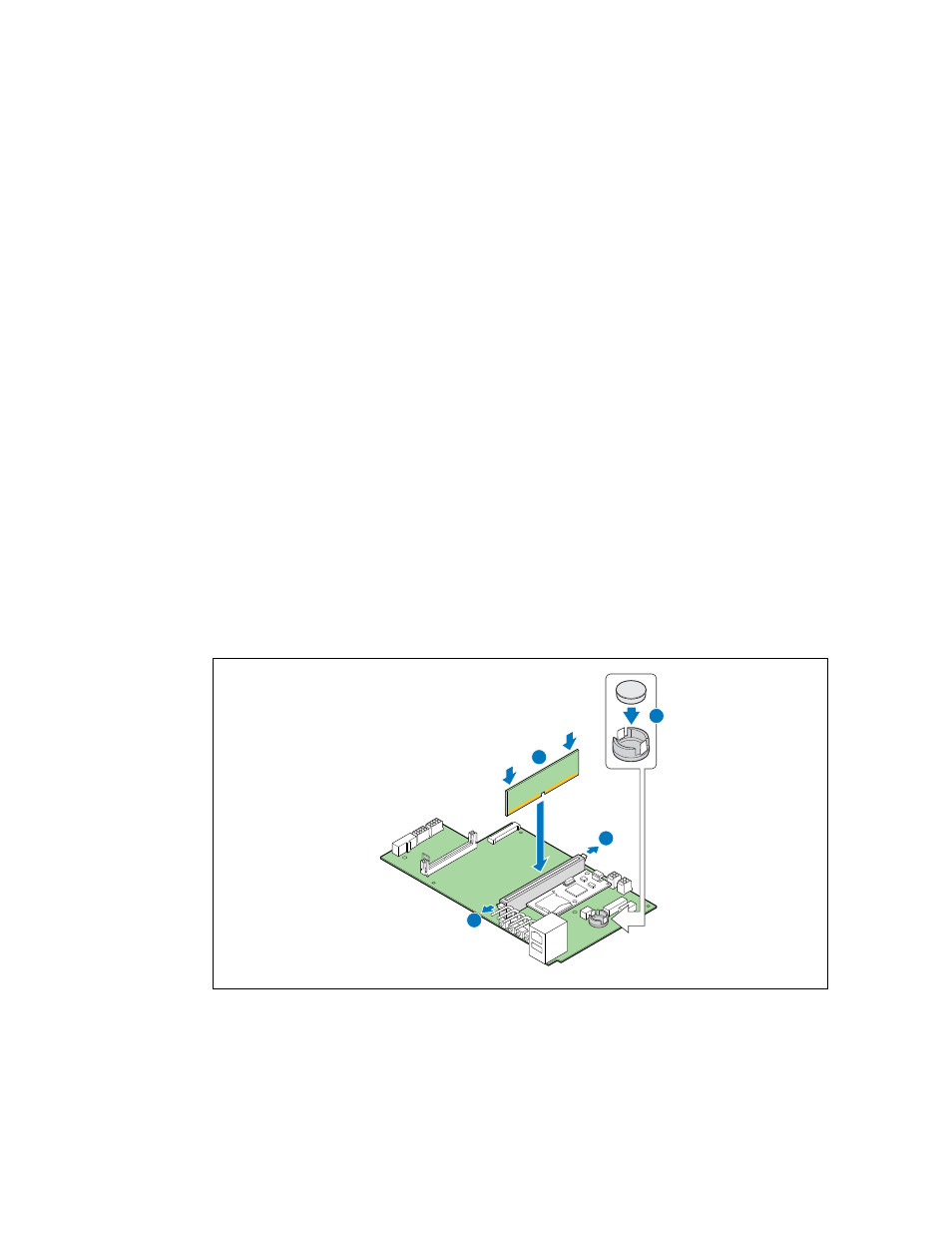
4. Open the latches on both ends of the RAID DIMM connector header. (“A”)
5. Note the location of the alignment notch (“B”) and insert the DIMM. Make sure the edge
connector on the DIMM aligns properly with the connection header.
6. Using both hands, press down firmly and evenly on both sides of the DIMM until it snaps into
place and the latches at each end close.
7. Insert the RAID activation key. (“C”) The wider rim is the top of the key. Make sure the metal clips
on the socket snap securely over the edge of the Activation Key top rim.
8. If you removed the TAM board, reiinstall it. For instructions, see
Section 5.3.3, “Installing the TAM
.
Figure 47.
Installing the RAID DIMM and the RAID Activation Key
TS000284
A
A
B
C