14 hard drive(s) are not recognized, 5 led information, Led information – Kontron TIGH2U Carrier Grade Server User Manual
Page 115: Section 7.5, For a descri
Kontron Carrier Grade Server TIGH2U
December 2009
Product Guide, rev.1.2
115
Troubleshooting—TIGH2U Server
7.4.13
Devices are not Recognized under Device Manager (Windows*
OS)
The Windows* operating systems do not include all of the drivers for the chipsets, onboard NICs, and
other components. See
r a link to the current drivers and chipset files.
7.4.14
Hard Drive(s) are not Recognized
Check the following:
Make sure the drive is not disabled in BIOS Setup.
Make sure the drive is compatible. Go to
for a link to the list of tested drives.
Make sure you have not exceeded the power budget for the server. Go to
for a link to software to check your power budget.
7.5
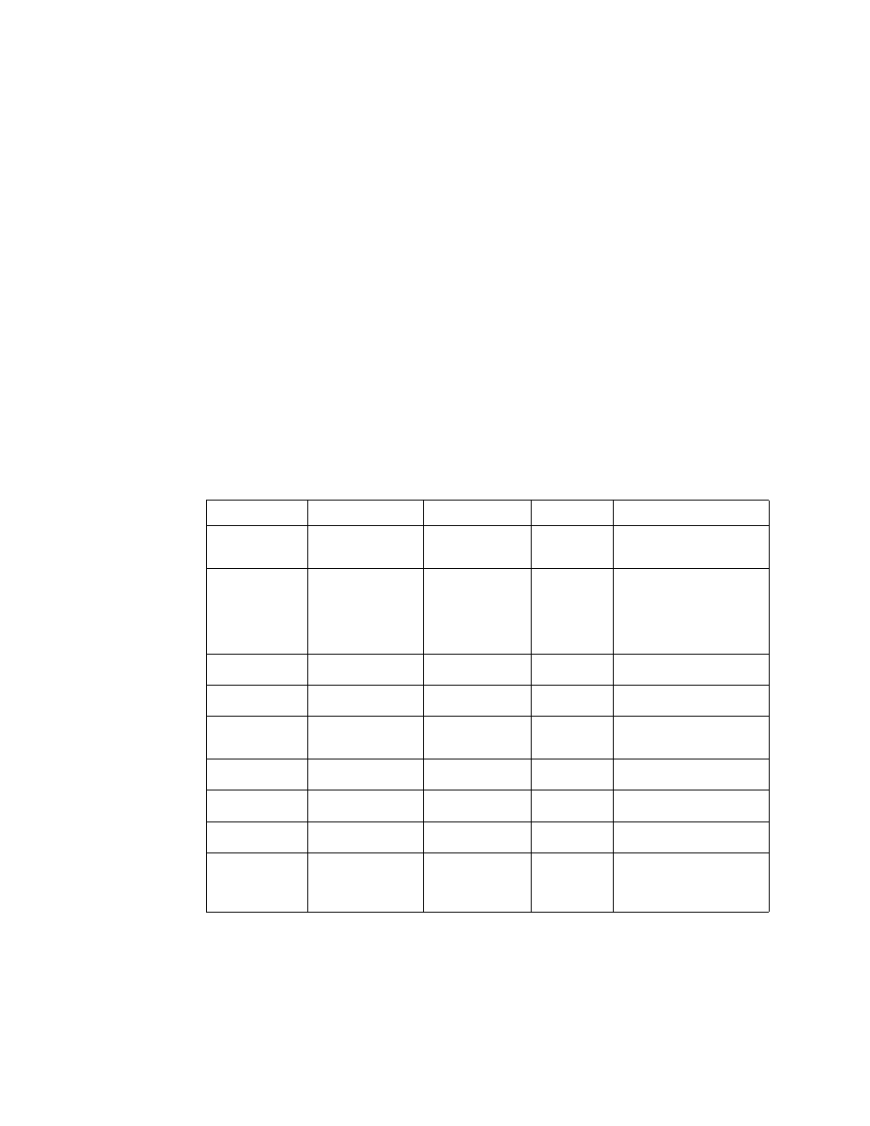
LED Information
The Intel
®
Server Board T5000PAL includes LEDs that can aid in troubleshooting your system.
defines these LEDs with a description of their use.
Table 14.
LED Definitions
LED Name
Function
Location
Color
Notes
ID
Aid in server
identification from
the back panel
Control panel and
rear left corner of
server board
Blue
Press ID LED button or user
Server Management
software to turn on the LED.
System fault
Visible fault warning
Control panel and
rear left corner of
server board
Green or
amber
Green = No Fault
Green blinking = degraded
Amber = critical error or
non-recoverable
Amber blinking = non-
critical error
ATA drive activity
Control panel
Control panel
Green
Blinking = Activity. No action
required.
Memory fault 1–6
Identify failing
memory module
DIMM end rear of
server board
Amber
On = Fault
Diagnostic LEDs.
1–4 (LSB, bit1,
bit2, MSB)
Displays port 80
POST codes
Center back edge
of server board
Each LED can
be off, green,
amber, red
See the POST code table
CPU 1 and 2
Fan Fault
Identify fan failure
Front center of
server board
Amber
On = Fault
CPU 1 and 2
Fault
Identify processor
failure
1 inch behind
processor socket
Amber
On = Fault
5v Standby
Identify 5v standby
power on state
Front left of server
board
Amber
On = 5v standby power on
Power LED
Identify the power
state of the system
Control Panel
Green
Off = Power is off (off or S5)
On = Power on or S0)
Slow Blink = Low power
state (S1 – S3)