3 installing or replacing a dc power supply, 4 grounding a dc-powered system, 1 configuring jumpers on the server board – Kontron TIGH2U Carrier Grade Server User Manual
Page 34: Installing or replacing a dc power supply, Grounding a dc-powered system, Configuring jumpers on the server board
TIGH2U Server—Server Component Installations and Upgrades
Kontron Carrier Grade Server TIGH2U
Product Guide, rev.1.2
December 2009
34
3.3.2.3
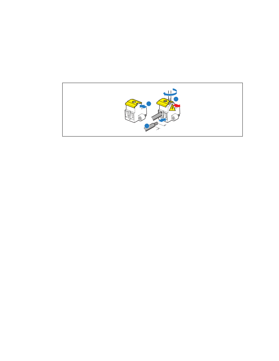
Installing or Replacing a DC Power Supply
1. Slide open top of male connector to reveal screw holes. ("A")
2. Strip the wire insulation as shown. Note minimum wire gauge. ("B")
Insert each wire all the way and tighten to 24 in-lb (2.7 N-m) torque. ("C")
Figure 18.
DC Power In Male Connector Configuration
Strip Wire 0.625"
(16mm)
Min. Wire
14 AWG
C
A
B
#2 Phillips*
Screwdriver
3.3.2.4
Grounding a DC-Powered System
The DC chassis provides two #10-32 threaded studs for chassis enclosure grounding. A single 90º
standard barrel, two-hole, compression terminal lug with 5/8-inch pitch suitable for a #14-10 AWG
conductor (such as the Thomas & Betts* terminal lug, p/n 256-31426-141) must be used for proper
safety grounding. See “C” in
for the location of the ground studs.
A crimping tool may be needed to secure the terminal lug to the grounding cable.
3.4
Internal System Component Configuration and Installation
Procedures
Note:
The procedures in this section assume that you have powered down the server and
removed the chassis cover as described in
3.4.1
Configuring Jumpers on the Server Board
The jumpers are located on the T5000PAL server board, which is in the rear right section of the
Carrier Grade Server TIGH2U chassis. To configure the jumpers on the server board, you must first
remove the chassis cover, the processor air duct (see
), and the PCI riser card assembly (see
Section 4.2.2, “Removing the PCI Riser Card Assembly”
). All other components installed on the server board can remain in place.