Advanced startup procedure, Advanced startup procedure -7 – Rockwell Automation 2364F Regenerative DC Bus Supply Unit (RGU) User Manual
Page 91
Publication 2364F-5.01– October 2003
Setting Up Your RGU
8-7
Advanced Startup Procedure
The advanced startup procedure may be performed after the basic
startup has been completed to configure the RGU for optimum
performance. A HIM, GPT, or other programming device will be
required to complete the advanced startup below.
Host Mode [P35]
The bits in the host mode parameter select current limiting functions in the current regulator.
Regen OnlyLimits the motoring current to 10% (regenerative current limit remains at 150%).
Err LimiterLimits the gain, step, and value allowed in the bus voltage error.
LinearizerAdjusts the current command so the bus voltage corresponds with the line voltage.
Note: The Err Limiter bit should be set to zero if the RGU is connected to any 1336 FORCE or SA3100
drives. Doing so will prevent overvoltage trip problems in the drives.
Id Current Command [P102]
The Id current command determines the amount of reactive current that the RGU should allow. Typically, this
value should be set to 0.0% (default).
For applications requiring reactive current, P102 can be adjusted from 60% lagging to -40% leading power
factor. If a non-zero value is given as the Id current command, the RGU will run at that percentage of reactive
current from the rated AC line current, even if the RGU is unloaded.
Note that reactive current in the RGU takes away from the active, work-producing current (Iq), and reduces
efficiency of the RGU.
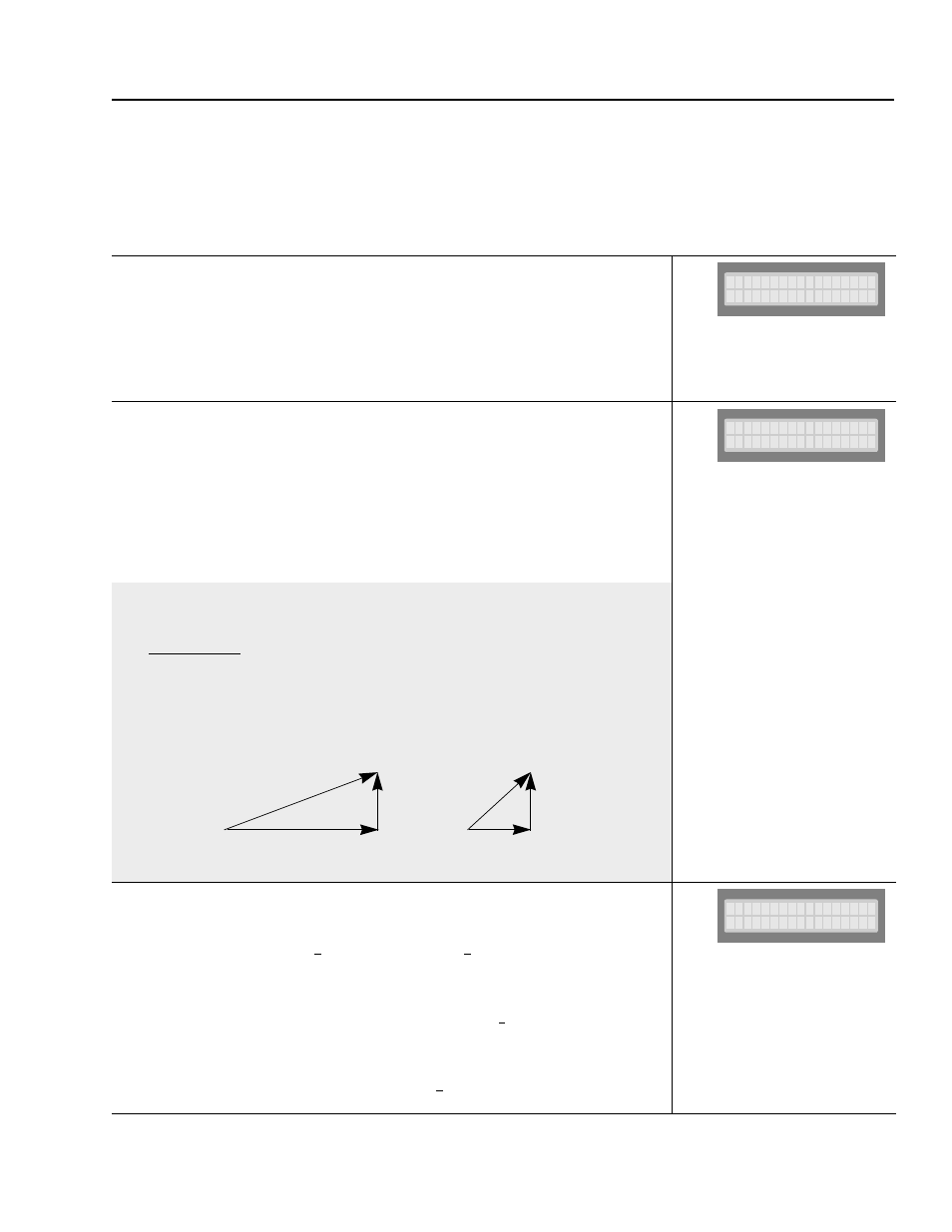
Example
If an RGU is set with a -40% leading reactive current (Id), the available active current (Iq) could be determined
in the formula (%Id² + %Iq² = %I
total
²).
%Iq =
√ (100%)² - (40%)² = 92% (Example Only) [%I
total
=100%]
At full load, the total current would be 100%, but the active (work-producing) current would only be 92%.
Since P102 only determines the amount of reactive current that the RGU will produce (not regarding the load),
the RGU would operate at a power factor of 0 (at no load) and increase to a power factor of -0.92
(at full load).
Voltage Mode Select [P123]
This parameter determines the voltage command that should be supplied to the regulator. The default, ‘Bus
Ref Auto’, selects the value from the Bus Reference Automatic (P129), which is calculated by:
P129 = (Measured AC Line Voltage) x
√2 x 1.05 i.e. P129 = 460 x √2 x 1.05 = 683V DC
To maintain the bus at a constant voltage, independent of the AC line voltage, the ‘Aux Volt Cmd’ or
‘Bus Volt Cmd’ may be selected. However, note that the RGU will not operate at 1.0 power factor if the
the specified voltage is less than the peak of the AC line (AC line voltage x
√2).
For example, if an RGU is supplied with 460V AC input, but the DC voltage command is set to 640V DC, the
RGU would be forced to operate with a some lagging current, which would reduce the efficiency of the RGU.
In this case, a voltage command greater than 651V DC (460 x
√2) would be a better choice.
H o s t
M o d e
x
x
x
x
x
x
x
x
x
1
x
0
x
0
x
0
0 . 0 %
I d
C o m m a n d
B u s
R e f
A u t o
V o l t
M o d e
S e l
Total
Current
Active
Current
Reactive
Current
Total
Current
Active
Current
Reactive
Current
The reactive current
remains constant.
Full Load
Small Load