Rockwell Automation 2364F Regenerative DC Bus Supply Unit (RGU) User Manual
Page 181
Publication 2364F-5.01– October 2003
Programming Parameters
D-37
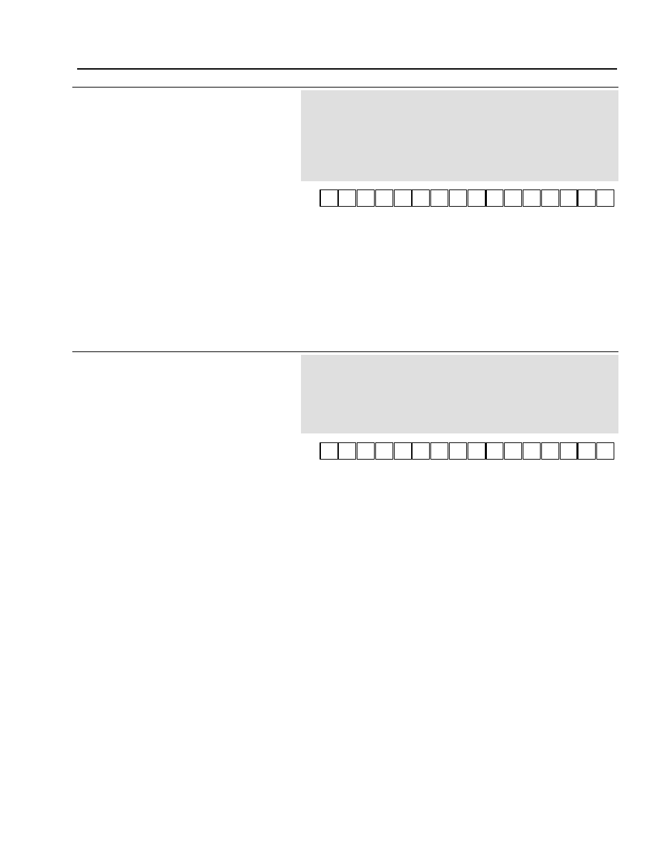
179
Fault/Warning Select Mask 2
[Fault/Warn Mask2]
This parameter determines whether conditions
should be reported as a warning (0) or handled as
a fault (1).
The factory default, for example, shows that
all the usable bits cause faults.
Parameter Type
Sink (Read/Write)
Display Units
None
Drive Units
Display Units * 1
Factory Default
1001 1100 0111 1111
Minimum Value
0000 0000 0000 0000
Maximum Value
1111 1111 1111 1111
Related Parameters
P174, P176
Bit
Description
Bit
Description
0*
Desaturizatn
Selects response to desaturization condition.
8
Not Used
1*
Board Intlk
Selects response to a board interlock condition.
9
Not Used
2*
HW Bus OverV Selects response to bus overvoltage (hardware).
10*
SW Line I
Selects response to line current condition (software).
3*
HW Line I
Selects response to current condtn (hardware).
11*
I Offset Err
Selects response to current offset error.
4*
Zero Seq Err
Selects response to zero sequence error.
12*
DualPort TO
Selects response to dual port timeout.
5*
Phase Lock L
Selects response to phase lock loop condition.
13
Not Used
6*
Phase Loss
Selects response to phase loss in AC line.
14
Not Used
7
Not Used
15*
DSP Fault
Selects response to DSP fault.
* These items cannot be changed to zero.
180
Host Fault Status Word 3
[Fault Status 3]
This parameter indicates a number of host fault
conditions.
1 - Fault
0 - No Fault
Parameter Type
Source (Read Only)
Display Units
None
Drive Units
Display Units * 1
Factory Default
0000 0000 0000 0000
Minimum Value
0000 0000 0000 0000
Maximum Value
1111 1111 1111 1111
Related Parameters
P181, P182
P181 and P182 determine what conditions are
reported and how the conditions are to be
handled (warning/fault).
Bit
Description
0
Clock Loss
Indicates that a reset has occurred due to loss of oscillator.
1
Double Bus
Indicates a memory access error.
2
Watchdog
Indicates a expiration fault in the watchdog timer.
3
En at Pwr Up
Indicates that the RGU was Enabled at power up.
4
Battery Low
Indicates that the battery for the battery-backed memory is low.
5
TIO Loss
Indicates that the primary control loop clock has been lost.
6
R2R Dup Addr
Indicates that more than one RGU (in a parallel application) have the same R2R transmit address (P267).
7
Lost Master
Indicates that communication to the master has been lost.
8
DPRAM Error
Indicates a fault in the dual port between the host and DSP.
9
No Vloop Tic
Indicates that the voltage loop clock has been lost.
10
No Fast Task
Indicates that high speed control tasks have stopped.
11
No Bgnd Task
Indicates that background tasks are not executing.
12
Addr Bus Err
Indicates an error in the address bus.
13
Data Bus Err
Indicates an error in the data bus.
14
Line Low
Indicates that the AC line voltage has dropped below the AC Line Low Setting (P26).
15
Line High
Indicates that the AC line voltage has exceeded the AC Line High Setting (P27).
Bit
8
Bit
9
Bit
10
Bit
11
Bit
12
Bit
13
Bit
14
Bit
15
Bit
0
Bit
1
Bit
2
Bit
3
Bit
4
Bit
5
Bit
6
Bit
7
Bit
8
Bit
9
Bit
10
Bit
11
Bit
12
Bit
13
Bit
14
Bit
15
Bit
0
Bit
1
Bit
2
Bit
3
Bit
4
Bit
5
Bit
6
Bit
7