D-10 programming parameters, Quick reference chart – Rockwell Automation 2364F Regenerative DC Bus Supply Unit (RGU) User Manual
Page 154
Publication 2364F-5.01– October 2003
D-10
Programming Parameters
36
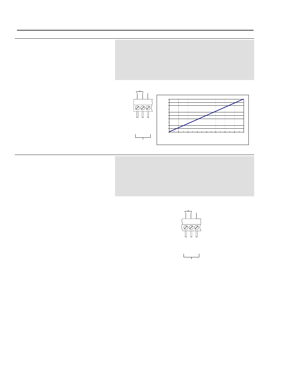
A/D Converter 0 Input
[ADC0 Input]
This parameter provides the diagnostics from the
ADC0 input ( TB1-1, TB1-2, TB1-3 [gnd]).
An external analog device can be wired to the
ADC0 input. The analog voltage (±10V) sent by
the device is sampled by a 14-bit analog-to-digital
converter (ADC) and the resulting value is stored
in this parameter.
Parameter Type
Source (Read Only)
Display Units
None
Drive Units
Display Units * 1
Factory Default
0
Minimum Value
-8191 (-10V signal)
Maximum Value
8191 (+10V signal)
Related Parameters
P37
See Pages
7-6, 11-1
The value of this parameter provides a digital
representation of the analog input which can then
be used by other parameters (to read the device
status, perform calculations, etc.).
The quick reference chart can be used to convert
the display values into analog input voltage.
37
A/D Converter 1 Input
[ADC1 Input]
This parameter provides the diagnostics from the
ADC1 input ( TB1-4, TB1-5, TB1-6 [gnd]).
An external analog device can be wired to the
ADC1 input. The voltage (±10V) sent by the
device is sampled by a 14-bit analog-to-digital
converter (ADC) and the resulting value is stored
in this parameter.
Parameter Type
Source (Read Only)
Display Units
None
Drive Units
Display Units * 1
Factory Default
0
Minimum Value
-8191 (-10V signal)
Maximum Value
8191 (+10V signal)
Related Parameters
P36
See Pages
7-6, 11-1
The value of this parameter provides a digital
representation of the analog input which can then
be used by other parameters (to read the device
status, perform calculations, etc.).
The listing for P36 shows a quick reference chart
for converting the display values into the analog
input voltage.
TB 1
1
2
3
A
n
a
lo
g
In
1
(
-)
A
n
a
lo
g
In
1
(
+
)
A
n
a
lo
g
I
n
1
(
C
o
m
)
To A nalog
D evice
T o AD C 0
G nd
-10
-8
-6
-4
-2
0
2
4
6
8
10
-8200
-6150
-4100
-2050
0
2050
4100
6150
8200
ADC Display Values
A
n
a
lo
g
Input
Vo
lt
a
g
e (
V
DC
)
Quick Reference Chart
TB 1
4
5
6
A
n
a
lo
g
In
2
(
-)
A
n
a
lo
g
In
2
(
+
)
A
n
a
lo
g
I
n
2
(
C
o
m
)
To A nalog
Device
To A D C 1
G nd