Rockwell Automation 2364F Regenerative DC Bus Supply Unit (RGU) User Manual
Page 158
Publication 2364F-5.01– October 2003
D-14
Programming Parameters
48
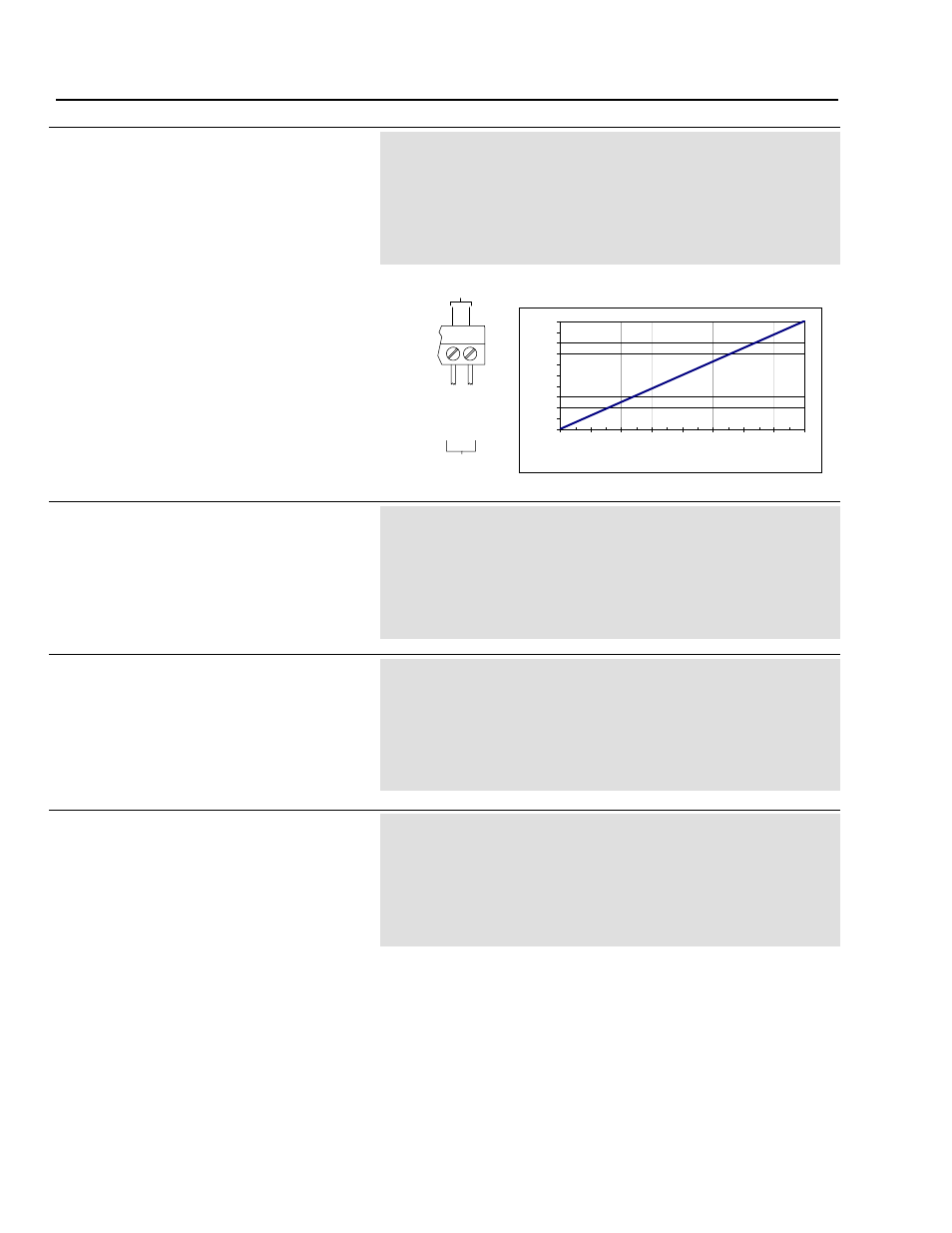
D/A Converter 2 Output
[DAC2 Output]
This parameter contains the value that is to be
sent to the digital-to-analog converter, then to
Analog Out 2 ( TB1-9, TB1-10 [com]).
The display value (-2048 to 2047) represents the
digital value, which is proportional to the voltage
sent through Analog Out 2 (-10V to +10V).
Parameter Type
Source (Read Only)
Display Units
None
Drive Units
Display Units * 1
Factory Default
0
Minimum Value
-2048 (-10V signal)
Maximum Value
2047 (+10V signal)
Related Parameters
P53, P54, P55, P56
See Chapter
11
An external analog device can be wired to Analog
Out 2 (DAC2 Output), and can read the contents
of a parameter, selected by P53 (D/A Converter 2
Source).
The quick reference chart can be used to convert
the display value into the analog output voltage.
See the diagram for P46 (D/A Converter 1 Source)
for an example of how a source parameter is
processed for Analog Out.
49
D/A Converter 1 Source
[DAC1 Indirect]
This parameter identifies the parameter value
which will be sent to DAC1 and out to Analog Out
1. The P47 listing (D/A Converter 1 Output)
shows a diagram of the DAC process.
The default selection is P141 (Bus Feedback).
Parameter Type
Sink (Read/Write)
Display Units
Parameter Number
Drive Units
Display Units * 1
Factory Default
141 (Bus Feedback Parameter)
Minimum Value
0
Maximum Value
Maximum Defined Parameter Number
Related Parameters
P47, P50, P51, P52
See Chapter
11
50
D/A Converter 1 Offset
[DAC1 Offset]
This parameter determines the +/- adjustment to
the value being sent to DAC1 (which is indicated
by P49 [D/A Converter Source]). This offset is
applied before the gain (P51).
The P47 listing (D/A Converter 1 Output) shows a
diagram of the DAC process.
Parameter Type
Sink (Read/Write)
Display Units
None
Drive Units
Display Units * 1
Factory Default
0
Minimum Value
-32768
Maximum Value
32767
Related Parameters
P47, P49, P51, P52
See Chapter
11
51
D/A Converter 1 Gain
[DAC1 Gain]
This parameter determines the gain adjustment to
the value being sent to DAC1 (which is indicated
by P49 [D/A Converter Source]). This gain is
applied after the offset (P50).
The P47 listing (D/A Converter 1 Output) shows a
diagram of the DAC process.
Parameter Type
Sink (Read/Write)
Display Units
None
Drive Units
Display Units * 256
Factory Default
0.25
Minimum Value
-128.00
Maximum Value
128.00
Related Parameters
P47, P49, P50, P52
See Chapter
11
TB1
9
10
To Analog
Device
DAC2
A
n
a
lo
g
O
u
t
2
A
n
a
lo
g
O
u
t
2
(
C
om
)
Quick Reference Chart
-10
-8
-6
-4
-2
0
2
4
6
8
10
-2048
-1536
-1024
-512
0
512
1024
1536
2048
DAC Display Values
An
alog
Ou
tp
u
t V
o
ltag
e
(V
D
C
)