Programming parameters d-13, Quick reference chart – Rockwell Automation 2364F Regenerative DC Bus Supply Unit (RGU) User Manual
Page 157
Publication 2364F-5.01– October 2003
Programming Parameters
D-13
47
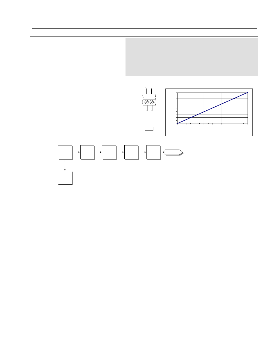
D/A Converter 1 Output
[DAC1 Output]
This parameter contains the value that is to be
sent to the digital-to-analog converter, then to
Analog Out 1 ( TB1-7, TB1-8 [com]).
The display value (-2048 to 2047) represents the
digital value, which is proportional to the voltage
sent through Analog Out 1 (-10V to +10V).
Parameter Type
Source (Read Only)
Display Units
None
Drive Units
Display Units * 1
Factory Default
0
Minimum Value
-2048 (-10V signal)
Maximum Value
2047 (+10V signal)
Related Parameters
P49, P50, P51, P52
See Chapter
11
An external analog device can be wired to Analog
Out 1 (DAC1 Output), and can read the contents
of a parameter, selected by P49 (D/A Converter 1
Source).
The quick reference chart can be used to convert
the display value into the analog output voltage.
The diagram below shows how the source
parameter value is processed using P49, P50,
P51, P52, P47, then sent to the DAC for Analog
Out.
TB1
7
8
A
n
a
lo
g
O
u
t
1
A
n
a
lo
g
O
u
t
1
(
C
om
)
To Analog
Device
DAC1
Quick Reference Chart
-10
-8
-6
-4
-2
0
2
4
6
8
10
-2048
-1536
-1024
-512
0
512
1024
1536
2048
DAC Display Values
An
alog
Ou
tp
u
t V
o
ltag
e
(V
D
C
)
P49
DAC1
Indirect
P50
DAC1
Offset
P51
DAC1
Gain
P52
DAC1
Cutoff Freq
P47
DAC1
Output
+/- adjustment to value
in source parameter
multiplier to value in
source parameter
adjusts the
frequency
sends the resulting
value to Analog Out 1
determines
source parameter
Pxxx
Source
Parameter
Analog Out 1