Rgu conceptual schematic, Rgu conceptual schematic -3 – Rockwell Automation 2364F Regenerative DC Bus Supply Unit (RGU) User Manual
Page 19
Publication 2364F-5.01– October 2003
Overview
1-3
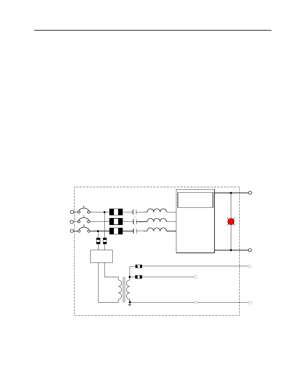
RGU Conceptual Schematic
The conceptual schematic shown in Figure 1.1 presents the basic
building blocks of your RGU.
The 3-phase, incoming AC power is applied to the inputs at the left of
the diagram. This input power is passed through the circuit breaker
(or motor circuit protector), line fuses, the main contactor, and AC
line reactors. These items ensure that the power structure receives
safe, clean power, protected from excessive currents or voltages.
The 3-phase power is then applied to the power structure (which is
controlled by the RGU control board). The power is converted to DC
through the power structure, and sent out the DC bus.
Two of the phases are tapped off the incoming power, and are passed
through line fuses and through a filter, and then transformed through
the control transformer. The secondary of this transformer supplies
control power to the RGU (including the bridge fan motor). As an
option, this power may be supplied to the control bus (fuses and an
appropriate control transformer are required).
Figure 1.1
Conceptual Schematic of the RGU
RGU
DC
Bus
Bus
Voltage
Light
AC Line
Reactors
Control
Transformer
Fuses
Circuit
Breaker
or MCP
3-Phase AC
Incoming
Power
L
L
N
N
RGU Control
Power
To Optional
Control Bus
RGU
Control Board
Power Structure
(This fuse included in
control power source
upgrade options.)
Main
Contactor
+
-
Filter