Module-defined data tags, Fault and alarm window – Rockwell Automation 1756-DMF30 ControlLogix Drive Module User Manual
Page 33
Publication 1756-UM522B-EN-P - February 2003
Drive Module Features
3-7
to direct data in a daisy chain configuration, In order to pass-through
buffered data, the local controller must intervene to move data along.
Module-Defined Data Tags
When you create a module, module-defined data types and tags are
created in the RSLogix 5000 programming software. These tags allow
you to access the Input and Output Data of the module via the
controller’s ladder logic, if necessary
The types of tags created vary, depending on which communications
format you choose when creating a module. There are two types of
tags:
•
Input Data Tags
•
Output Data Tags
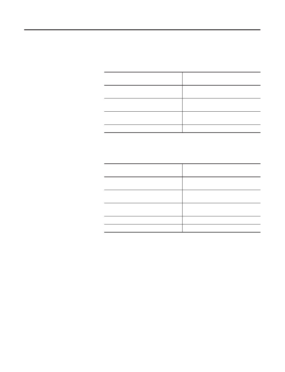
Table 3.A
Drive Module Receive Communications Formats
Receive Port Communications Format
Transfer Rate (across the fiber optic
cable) for Each Data Type:
2 Direct Words, 18 Buffered
Direct Data - Updated every 50
µ
S
Buffered Data - Updated every 250
µ
S
4 Direct Words, 18 Buffered
Direct Data - Updated every 50
µ
S
Buffered Data - Updated every 500
µ
S
4 Direct Words, 8 Buffered
Direct Data - Updated every 50
µ
S
Buffered Data - Updated every 250
µ
S
No Receive Data
No data updated in this format
Table 3.B
Drive Module Transmit Communications Formats
Transmit Port Communications Format
Transfer Rate (across the fiber optic
cable) for Each Data Type:
2 Direct Words, 18 Buffered
Direct Data - Updated every 50
µ
S
Buffered Data - Updated every 250
µ
S
4 Direct Words, 18 Buffered
Direct Data - Updated every 50
µ
S
Buffered Data - Updated every 500
µ
S
4 Direct Words, 8 Buffered
Direct Data - Updated every 50
µ
S
Buffered Data - Updated every 250
µ
S
Listen Only, No Transmit Data
No data updated in this format
No Transmit Data
No data updated in this format