Physical features of the controllogix drive module – Rockwell Automation 1756-DMF30 ControlLogix Drive Module User Manual
Page 18
Publication 1756-UM522B-EN-P - February 2003
1-4
What is the ControlLogix Drive Module?
Before you install and use your module you should have already:
•
installed and grounded a 1756 chassis and power supply. For
more information, refer to the publications listed in Table 1.D.
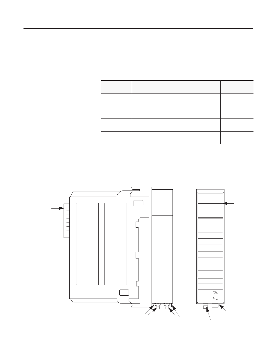
Physical Features of the ControlLogix Drive Module
Table 1.D
Chassis and Power Supply Documentation
Catalog
number:
Document title:
Pub. number:
1756-A4, -A7,
-A10, -A13
ControlLogix Chassis Installation Instructions
1756-IN080
1756-PA72,
-PB72
ControlLogix Power Supply Installation Instructions 1756-5.67
1756-PA75,
-PB75
ControlLogix Power Supply Installation Instructions 1756-5.78
1756-PA75R/A,
-PB75R/A
ControlLogix Redundant Power Supply Installation
Instructions
1756-IN573
ControlBus
Connector-
Interface to the
ControlLogix
system
backplane
Status
Indicators
Module side view
Module front view
LINK
COMM
LINK
SYNC
DRIVE
COMM OK
DRIVE
FAULT
OS OK
OK
SD3000 INTERFACE
Tx (rear)
Rx (front)
Drive
Communication
Ports
SynchLink
Ports
Receive Ports
(in front)
Transmit Ports
(in back)
The 1756-DMD30, SD3000 Interface, is shown. Physical
features are common to all ControlLogix Drive Modules.