Configuration, Chapter 2 installation/wiring, Figure 2.34. plc comm adapter links – Rockwell Automation 1336T FORCE Series B User Manual
Page 66: 1336 force remote i/o interface, Plc controller
Chapter 2
Installation/Wiring
2–46
Configuration
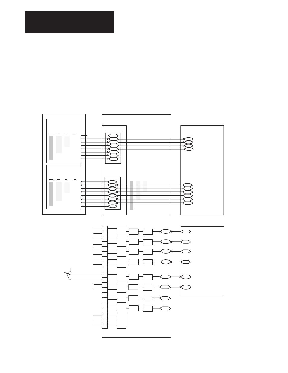
The 1336 FORCE Drive is shipped pre-configured, which means that some
of the inputs and outputs are linked to a predefined signal. Figure 2.34
shows the 1336 FORCE standard configuration when equipped with a PLC
Communication Adapter Board. The user has the flexibility to configure
the Drive for a particular application.
Figure 2.34.
PLC Comm Adapter Links
PLC Comm Adapter
Channel B
1
Logic CMD In Port 6
OUTPUT IMAGE TABLE
GROUP NUMBER
1336 FORCE
Remote I/O Interface
331
OFFSET
400
SCALE
Analog Outputs
Drive Parameters
TB21
1
Reserved For-
Block Transfer
PLC CONTROLLER
FULL
0/2
1/3
2/4
3/5
4/6
5/7
0/2/4
1/3/5
2/4/6
3/5/7
3/4
1/2
1/4
0/2/4/6
1/3/5/7
332
333
334
335
336
337
0
1
2
3
4
5
6
7
INPUT IMAGE TABLE
GROUP NUMBER
FULL
0/2
1/3
2/4
3/5
4/6
5/7
3/4
1/2
1/4
0/2/4/6
1/3/5/7
0
1
2
3
4
5
6
7
360
361
362
363
367
101
53
2
3
4
27
Drive
Parameters
Ext Vel Ref #1 Hi
Torque Mode Select
Process Trim Ref
56
269
264
265
364
365
366
182
266
1 – Full Rack
2 – 3/4 Rack
3 – 1/2 Rack
4 – 1/4 Rack
Logic Status Low
Filtered Vel Fdbk
Motor Current Fdbk
Computed Power
Motor Voltage Fdbk
Stator Frequency
2
3
4
5
6
7
8
+
–
+
–
+
–
+
–
9
10
11
12
13
15
14
16
18
17
19
–
+
–
+
–
+
–
+
COMM
401
387
OFFSET
402
SCALE
403
388
OFFSET
404
SCALE
405
389
OFFSET
406
SCALE
407
390
–
+10V
Common
–10V
Analog Inputs
OFFSET
392
SCALE
393
339
OFFSET
394
SCALE
395
340
OFFSET
316
SCALE
317
341
OFFSET
318
SCALE
319
342
Power
Supply
269
Filtered Vel Fdbk
182
Computed Power
264
Motor Current Fdbk
265
Motor Voltage Fdbk
104
Ext Vel Ref #2 Hi
28
Process Trim Fdbk
+
–
Proc Trim Fdbk
Ext Vel Ref #2 Hi
+
–
Filtered Vel Fdbk
Comm
Computed Power
Comm
Motor Current Fdbk
Comm
Motor Voltage Fdbk
Comm
330
359
0/2/4
1/3/5
2/4/6
3/5/7