As shown in – Rockwell Automation 1336T FORCE Series B User Manual
Page 116
Chapter 4
Startup
4–25
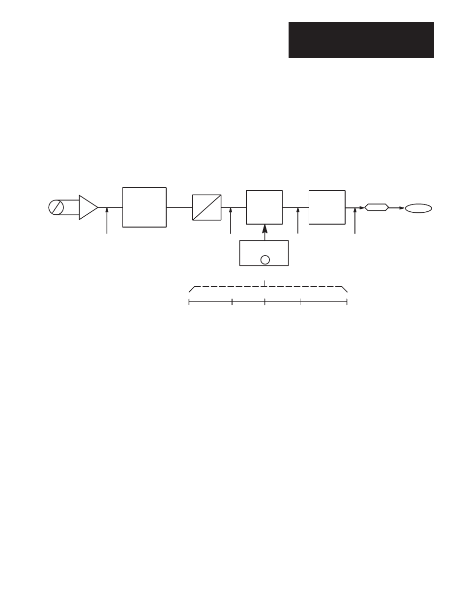
As shown in
Figure 4.9
, the offset voltage adds the corresponding digital
value to the range. In this case, an offset of –5 volts adds a digital value of
–1024 to the range. This causes 0 volts on the potentiometer to register as
–1024 digital internal to the drive and 10 volts on the potentiometer will be
+1024 to the drive. This can then be scaled by a factor of 4
(8192 drive units) so that 0 volts sends a digital value of –4096 for –100%
torque, and 10 volts sends a digital value of +4096 for +100% torque.
Figure 4.9.
Potentiometer 0–10V Range to Control +/– 100% Torque Reference
0–10V POT
0
10v
A
D
SCALE
0
to
2048
–1024
+1024
+4096
+4096
RANGE OF 20V
0
0
0
–10V
–2048
+10V
+2048
PAR 357
X 4
+0v
POTENTIOMETER
DIGITAL VALUE
OFFSET BY –5V
10V
–10V
5V
1024
0
0
–1024
–4096
+1024
+4096
ADDING –1024
SCALE BY 4
PAR 162
±
2048
(=
±
10V)
OFFSET
Par 356 = –5V
Par 355
MULTIPLEXER
10V Input
Analog outputs are set up similar to analog inputs. Each output has a scale
and offset parameter, along with a specific variable parameter used for
linking. Differences occur because of the direction of information flow. The
drive sends a digital value in drive units, which must be matched to the
voltage of the monitoring device. Similar to analog inputs, the analog output
converts a
±
2048 to
±
10VDC. Thus, when the drive sends
±
100% Base
Speed (equal to
±
4096) it must be scaled by 0.5 to be in the proper range
(
±
4096
×
0.5 =
±
2048). Offset can be
±
20VDC, even though the physical
limit is
±
10VDC. This allows you to offset the signal anywhere within the
entire range.