Figure 4.5 master/ slave communication example – Rockwell Automation 1336T FORCE Series B User Manual
Page 110
Chapter 4
Startup
4–19
Receiver Example:
P16 Drive Receive Indirect 1 – Any VP/CP Parameter
or – P22 (Receive 1, Data 1)
P22 would then have a value or a non VP/CP parm linked to it.
Data – The D2D TX and RX data exists as non VP parameters in the
parameter table. This allows data outside the Motor Control Board to get
access to the D2D. Data parameter examples were shown in the previous
transmitter and receiver examples.
Master/ Slave Drive to Drive Communication – Figure 4.5 illustrates
an example of D2D applied to a master/slave drive set up. The master
drive receives its speed reference from a speed pot wired to analog input 1
on a PLC Comm board. P339 (Analog In1) is linked to P101 (Ext Vel Ref)
on the master drive. P392 (Analog In 1 Offset) and P393 (analog In1
Scale) are set accordingly. Analog Input 1 must be passed from the master
drive to the slave drive and connected to the P101 (Ext Vel Ref) using the
D2D protocol.
Setting up the Master drive requires that a transmit address be chosen. An
address 1 is chosen in this example. P14 (Drive Xmit Indirect 1) will have
a value of 20 entered into it (which means look to P20 (Drive Xmit Data
1)). P20 (Drive Xmit Data 1) must be linked to P339 (Analog In1). This
is where the data comes from that will be transmitted.
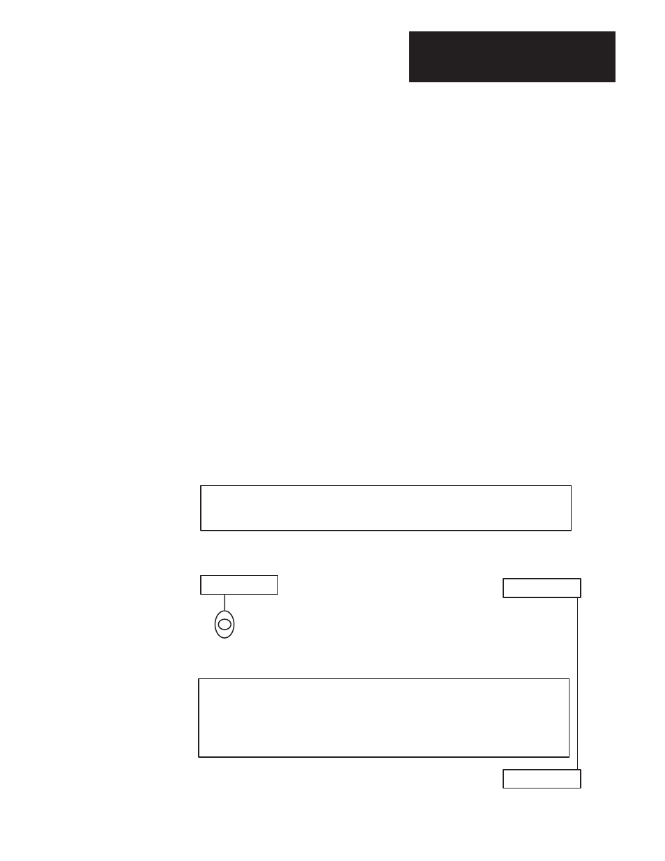
Figure 4.5
Master/Slave Communication Example
Master
P11 Drive Xmit Address – Transmitter Station Address – 1
P14 Drive Xmit Indirect 1 – VP/CP Parm. or P20
–20
P20 Drive Xmit Data 1 – Non VP/CP Parm
Linked – 339 (Analog In 1)
P339 (Analog In 1) linked P101) (Ext Vel Ref)
P392 (Analog In1 Offset)
P393 (Analog In 1 Scale)
Drive to Drive
Analog Inputs
0 – 10V
Slave
P12 Drive Receive 1 Address – Transmitter you are getting data from – 1
P16 Drive Receive Indirect 1 – VP/CP Parm. or P22 –101
(Ext Vel Ref)
P102 (Vel Scale Factor)
Used to Control Gear Ratio
Drive to Drive