Rockwell Automation 1336T FORCE Series B User Manual
Page 117
Chapter 4
Startup
4–26
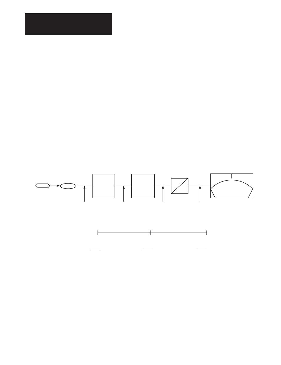
In
Figure
4.10 Analog Output 1 is used as an example to detail the scaling
and offset parameters. At Analog Output 1 a meter with a range of 0-10 V
DC has been connected. Parameter 370 has been linked to Parameter 146
(Velocity Feedback). In order for the meter to indicate speed in both
directions, the scale and offset parameters must be adjusted as shown in
Figure
4.10. Working in the opposite direction as the analog inputs, apply the
scale factor first. The drive sends a
±
4096 digital value to indicate
±
100%
velocity feedback for a total digital range of 8192. The meter, having an
analog range of 0-10V
DC, requires a digital range of 2048. This is
accomplished by applying a scale factor of 0.25 (8192
×
0.25 = 2048).
In order to have the 0-10V
DC meter indicate
±
100% feedback, an offset
must be applied. Offset parameters for analog outputs will again add the
corresponding digital value to the range. In this case, an offset of 5 volts adds
a digital value of 1024 to the range. This will allow full range deflection on
the 0 to 10 volt meter, with 5 volts indicating zero speed.
Figure 4.10.
Analog Output 1 +/– 100% Speed Indication
–100%
B. SPD.
0 SPD.
+100%
B. SPD
5V
0V
10V
+4096 (+100% SPEED)
0
–4096 (–100% SPEED)
+1024
0
–1024
+2048
+1024
0
+10V = + 100% BASE SPEED
+5V = 0 SPEED
SCALE
PAR 372
X 0.25
OFFSET
PAR 371
5V = 1024
D
A
SCALED BY 0.25
0V = –100%
OFFSET BY 5V, ADDING 1024
DIGITAL VALUE
METER VOLTAGE
% BASE SPEED
– 4096
– 1024
+ 1024
0
0 VOLTS
– 100%
0
0
+ 1024
0
5 VOLTS
0%
4096
+ 1024
+ 1024
2048
10 VOLTS
+ 100%
(
±
2048 =
±
10V)
PAR 146
PAR 370
VELOCITY
FEEDBACK
ANALOG OUT 1
DIGITAL RANGE
FROM DRIVE