Chapter 4 startup – Rockwell Automation 1336T FORCE Series B User Manual
Page 125
Chapter 4
Startup
4–34
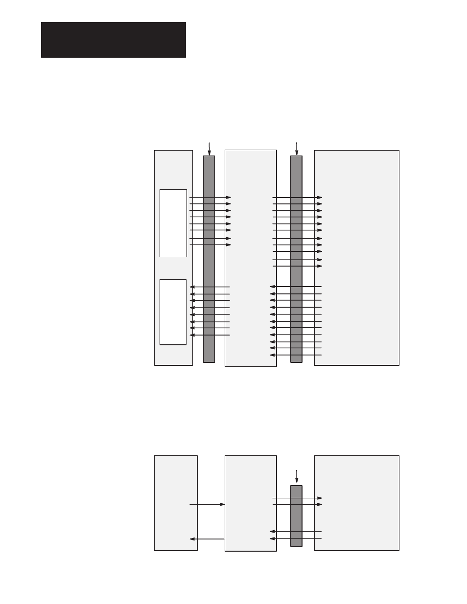
Remote I/O Communications Module:
The following figure shows how the I/O image table for the programmable
controller relates to the 1336 FORCE drive when a Remote I/O
Communications Module is used.
Remote I/O
Communications
Module
Block Transfer
Logic Command
Reference
Datalink A1
➀
Datalink A2
➀
Datalink B1
➀
Datalink B2
➀
Datalink C1
➀
Datalink C2
➀
Datalink D1
➀
Datalink D2
➀
Block Transfer
Logic Status
Feedback
Datalink A1
➀
Datalink A2
➀
Datalink B1
➀
Datalink B2
➀
Datalink C1
➀
Datalink C2
➀
Datalink D1
➀
Datalink D2
➀
1336 FORCE Drive
Controller
PLC I/O
Image
Output Image
O:010
O:011
O:012
O:013
O:014
O:015
O:016
O:017
I:010
I:011
I:012
I:013
I:014
I:015
I:016
I:017
Input Image
Message Handler
Logic Evaluation Block
SP An 2 Sel (p. 367)
Data In A1 (p. 310)
Data In A2 (p. 311)
Data In B1 (p. 312)
Data In B2 (p. 313)
Data In C1 (p. 314)
Data In C2 (p. 315)
Data In D1 (p. 316)
Data In D2 (p. 317)
Message Handler
Logic Status LO (p. 56)
SP An Output (p. 379)
Data Out A1 (p. 320)
Data Out A2 (p. 321)
Data Out B1 (p. 322)
Data Out B2 (p. 323)
Data Out C1 (p. 324)
Data Out C2 (p. 325)
Data Out D1 (p. 326)
Data Out D2 (p. 327)
RIO
SCANport
➀
Optionally enabled using
DIP switches on the module.
8 words maximum
8 words maximum
Flex I/O Module:
The following figure shows how the I/O image table for the programmable
controller relates to the 1336 FORCE drive when a Flex I/O Module is
used.
1203–FM1
and 1203–FB1
Modules
Logic Command
Reference
➀
Logic Status
Feedback
1336 FORCE Drive
Flex
Adapter
Logic Evaluation Block
SP An 2 Sel (p. 367)
Logic Status Low (p. 56)
SP An Output (p. 379)
SCANport
RIO
DeviceNet
ControlNet
Others