Starting & stopping the motor, Chapter 2 installation/wiring, Figure 2.22. terminal block locations – Rockwell Automation 1336T FORCE Series B User Manual
Page 54
Chapter 2
Installation/Wiring
2–34
Starting & Stopping the Motor
ATTENTION: The 1336 FORCE Drive control circuitry includes
solid–state components. If hazards due to accidental contact with
moving machinery or unintentional flow of liquid, gas or solids
exist, an additional hardwired stop circuit is required to remove
AC line power to the drive. When AC input power is removed,
there will be a loss of inherent regenerative braking effect and the
motor will coast to a stop. An auxiliary braking method may be
required.
!
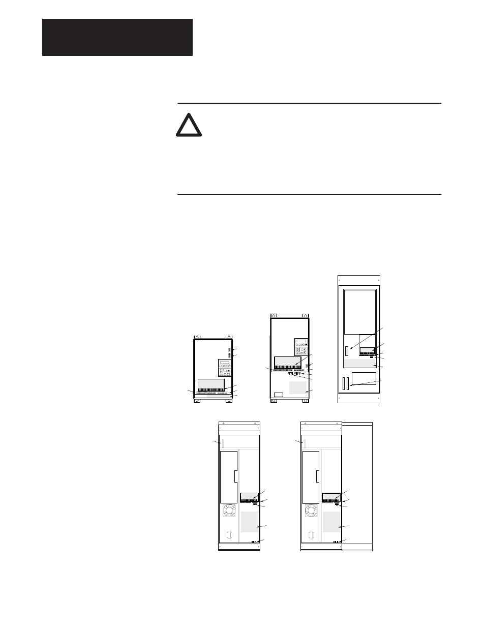
Figure 2.22 illustrates the location of the terminal blocks that are used for
interfacing control signals to a 1336 FORCE equipped with a Standard
Adapter Board.
Figure 2.22.
Terminal Block Locations
TB1
TB11
TB3
TB4
TB6
Power Terminal Block
Control & Signal Wiring
Control Interface Option
24V DC Auxiliary Input
High Voltage DC Auxiliary Input
480V Output (F Frame Only)
Shield Terminals
TB1
TB10, 11
TB3
TB4
TB6
TB9
TE
Frames B, C
Frames D, E
TB1
TB11
TB3
Control Interface
Option
Control Interface
Option
TB1
TB1
Location
TB1 Location
TB4
TB6
TE
TB1
Frame G
Frame F
U, V, W
& Brake
Terminals
TB10, 11
TB3
Brake
Terminals
R, S, T
TE
TE
PE
Ground
TB10, 11
TB3
TB9
TB1
Location
TB10
TB10
Frame H
U, V, W
& Brake
Terminals
TB10, 11
TB3
+, -
TE
PE Ground
TB1
Location
TB1
Power Terminal Block
TB10, 11 Control & Signal Wiring
TB3
Control Interface Option
TB4
(For Factory Use Only)
TB6
(For Factory Use Only)
TB9
480V Output (F Frame Only)
TE
Shield Terminals