Rockwell Automation 25-COMM-D PowerFlex 525 DeviceNet Adapter User Manual
Page 94
94
Rockwell Automation Publication 520COM-UM002A-EN-E - April 2013
Appendix B
Adapter Parameters
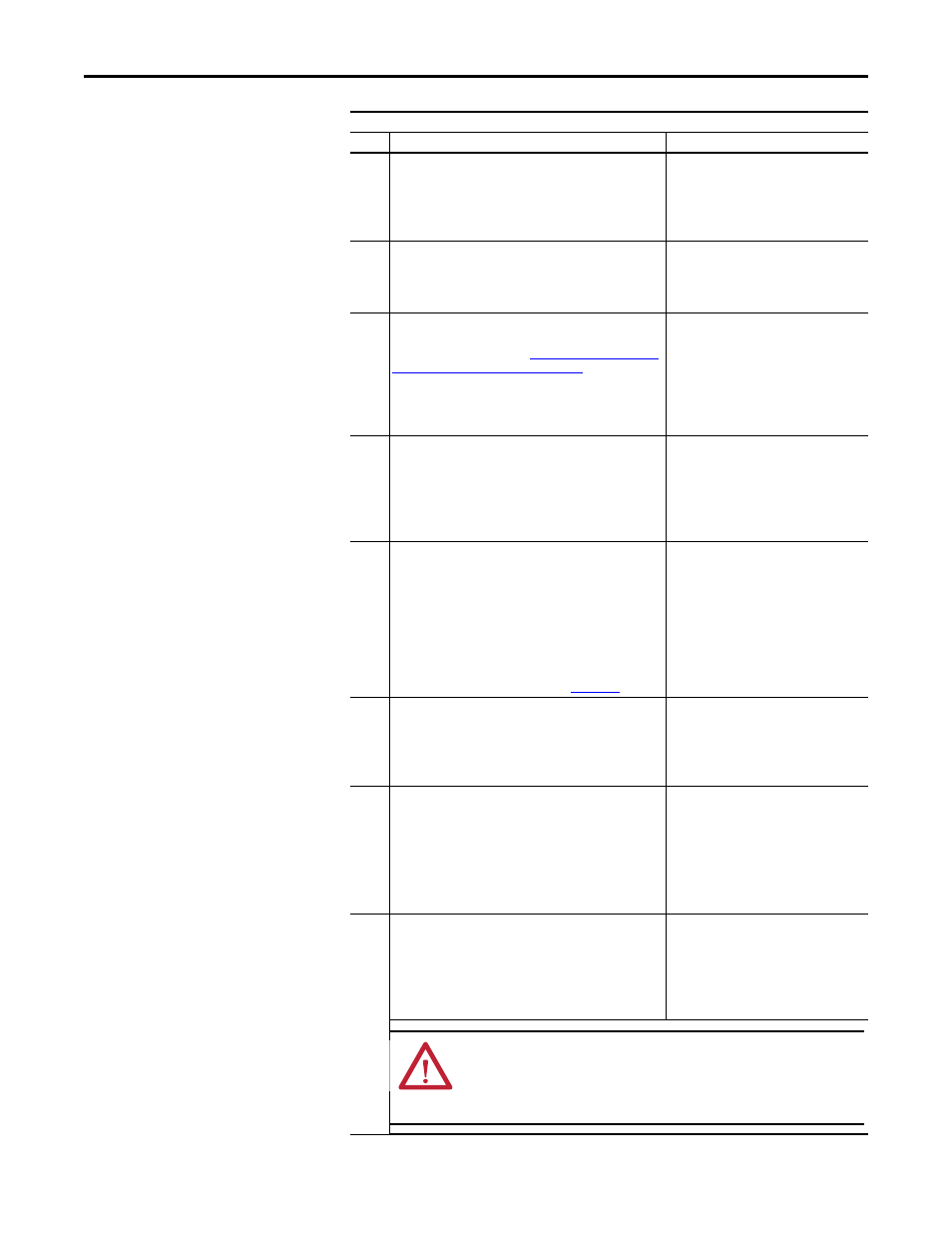
07
[Net Addr Cfg]
Sets the network node address for the adapter when Device
parameter 06 [Net Addr Src] is set to 1 “Parameters”.
Default:
63
Minimum:
0
Maximum:
63
Type:
Read/Write
Reset Required:
Yes
08
[Net Addr Act]
Displays the actual network node address used by the adapter.
Minimum:
0
Maximum:
63
Type:
Read Only
Reset Required:
No
09
[Net Rate Cfg]
Sets the network data rate at which the adapter communicates
when the Data Rate switch (See
Data Rate Using the DIP Switches on page 16
) is set to position
‘3’. (Updates Device parameter 10 [Net Rate Act] after a reset.)
Default:
0 = 125kbps
Values:
0 = 125kbps
1 = 250kbps
2 = 500kbps
3 = Autobaud
Type:
Read/Write
Reset Required:
Yes
10
[Net Rate Act]
Displays the actual network data rate being used by the
adapter.
Values:
0 = 125kbps
1 = 250kbps
2 = 500kbps
3 = Autobauding
Type:
Read Only
Reset Required:
No
11
[COS Status Mask]
Sets the mask for the 32-bit Logic Status word. Unless they are
masked out, the bits in the Logic Status word are checked for
changes when the adapter is allocated using COS (Change of
State). If a bit changes, it is reported as a change in the Change
of State operation.
If the mask bit is ‘0’ (Off), the bit is ignored. If the mask bit is ‘1’
(On), the bit is checked.
Important: The bit definitions in the Logic Status word for
PowerFlex 520-Series drives are shown in
.
Default:
0000 0000 0000 0000
0000 0000 0000 0000
Minimum:
0000 0000 0000 0000
0000 0000 0000 0000
Maximum:
1111 1111 1111 1111
1111 1111 1111 1111
Type:
Read/Write
Reset Required:
No
12
[COS Fdbk Change]
Sets the amount of acceptable error (positive or negative) that
the Feedback word can change before it is reported as a change
in the COS (Change of State) operation.
Default:
0
Minimum:
0.000
Maximum:
3.40282 x 10
38
Type:
Read/Write
Reset Required:
No
13
[COS/Cyc Interval]
Displays the amount of time that a scanner will wait to check
for data in the adapter.
When COS (Change of State) data exchange has been
configured, this is the maximum amount of time between
scans. Scans will occur sooner if data changes.
When Cyclic data exchange has been configured, this interval is
the fixed time between scans.
Minimum:
0.000 s
Maximum:
65.535 s
Type:
Read Only
Reset Required:
No
14
[Reset Module]
No action if set to 0 “Ready”. Resets the adapter if set to 1 “Reset
Module”. Restores the adapter to its factory default settings if
set to 2 “Set Defaults”. This parameter is a command. It will be
reset to 0 “Ready” after the command has been performed.
Default:
0 = Ready
Values:
0 = Ready
1 = Reset Module
2 = Set Defaults
Type:
Read/Write
Reset Required:
No
Parameter
No.
Name and Description
Details
ATTENTION: Risk of injury or equipment damage exists. If the adapter
is transmitting I/O that controls the drive, the drive may fault when you
reset the adapter. Determine how your drive will respond before
resetting the adapter.