Multi-drive mode – Rockwell Automation 25-COMM-D PowerFlex 525 DeviceNet Adapter User Manual
Page 70
70
Rockwell Automation Publication 520COM-UM002A-EN-E - April 2013
Chapter 7
Using Multi-Drive Mode
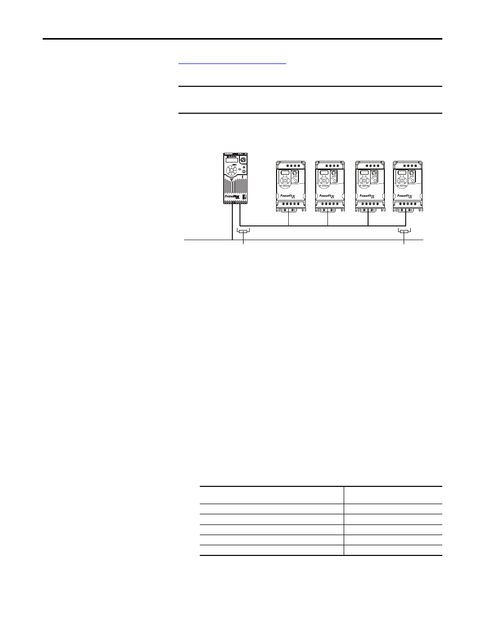
Example for Network on page 70
). The first drive must be a PowerFlex 525 drive.
The remaining drives can be any PowerFlex drive which supports Multi-drive.
Multi-Drive Mode Example for Network
Benefits of Multi-drive mode include:
•
Lower hardware costs. No need to purchase additional communication
adapters for daisy-chained drives.
•
Reduces the network node count. For example, in Single-drive mode 30
drives would consume 30 nodes. In Multi-drive mode, 30 drives can be
connected in 6 nodes.
•
Controller can control, monitor, and read/write parameters for all five
drives.
The trade-offs of Multi-drive mode include:
•
If the PowerFlex 525 with DeviceNet adapter is powered down, then
communications with the daisy-chained drives is disrupted and the drives
will take the appropriate communications loss action set in each drive.
•
Communications throughput to the daisy-chained drives will be slower
than if each drive was a separate node on DeviceNet (Single-drive mode).
This is because the DeviceNet adapter must take the DeviceNet data for
the other drives and sequentially send the respective data to each drive over
RS-485. The approximate additional throughput time for Logic
Command/Reference to be transmitted and received by each drive is:
IMPORTANT
For the examples in the chapter, we will use the PowerFlex 525 as a Master
drive with four daisy-chained PowerFlex 4M drives.
Drive
Additional Throughput Time
versus Single-Drive Mode
PowerFlex 525
0 ms
PowerFlex 525 plus 1 drive
+24 ms
PowerFlex 525 plus 2 drives
+48 ms
PowerFlex 525 plus 3 drives
+72 ms
PowerFlex 525 plus 4 drives
+96 ms
Esc
Sel
Up to 5 drives per node
DeviceNet
Up to four daisy-chained PowerFlex drives
(PowerFlex 4M shown)
RS-485 cable
PowerFlex 525
as master drive
AK-U0-RJ45-TB2P connector with
terminating resistor (120
Ω
)
AK-U0-RJ45-TB2P connector with
terminating resistor (120
Ω
)
AK-U0-RJ45-TB2P