Applying power, Start-up status indication – Rockwell Automation 25-COMM-D PowerFlex 525 DeviceNet Adapter User Manual
Page 20
20
Rockwell Automation Publication 520COM-UM002A-EN-E - April 2013
Chapter 2
Installing the Adapter
4.
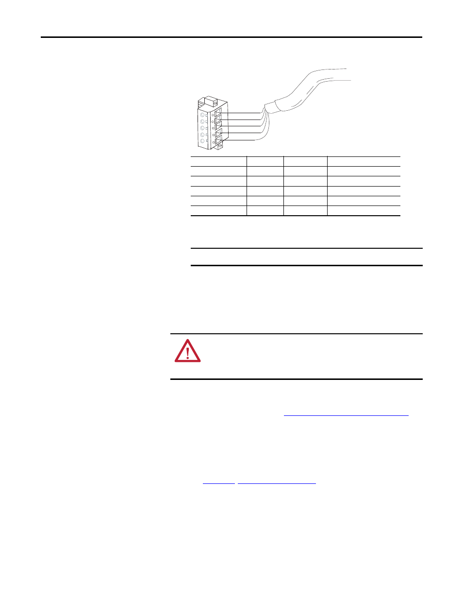
Connect the 5-pin linear plug to the DeviceNet cable.
5.
Insert the 5-pin linear plug into the mating socket on the adapter and
secure it with the two screws. Verify that the colors of the wires on the plug
match up with the color codes on the socket.
Applying Power
1.
Make sure that the adapter will have a unique address on the network and
is set at the correct data rate or to autobaud. If a new data rate or address is
needed, reset its switches (see
Commissioning the Adapter on page 15
).
2.
Apply power to the drive. The adapter receives its power from the
connected drive and network.
3.
If the parameter settings for the data rate and node address are to be used, a
configuration tool such as Connected Components Workbench (version 3
or greater) can be used to adjust the respective parameters in the adapter.
See
.
Start-Up Status Indication
After power has been applied, the status indicators can be viewed on the front of
the drive. When you apply power to the product and network for the first time,
TIP
A 5-pin linear plug is shipped with the adapter. If a replacement plug is
needed, the replacement plug part number is 1799-DNETSCON.
IMPORTANT
A 10-pin linear plug is not supported.
5
4
3
2
1
Red
White
Bare
Blue
Black
Terminal
Color
Signal
Function
5
Red
V+
Power Supply
4
White
CAN_H
Signal High
3
Bare
SHIELD
Shield
2
Blue
CAN_L
Signal Low
1
Black
V-
Common
ATTENTION: Risk of equipment damage, injury, or death exists. Unpredictable
operation may occur if you fail to verify that parameter settings are compatible
with your application. Verify that settings are compatible with your application
before applying power to the drive.