Understanding the i/o image, Using logic command/status, Using reference/feedback – Rockwell Automation 25-COMM-D PowerFlex 525 DeviceNet Adapter User Manual
Page 48
48
Rockwell Automation Publication 520COM-UM002A-EN-E - April 2013
Chapter 5
Using the I/O
Understanding the I/O Image
The terms
input and output are defined from the controller’s point of view.
Therefore, output I/O is data that is produced by the controller and consumed by
the adapter. Input I/O is status data that is produced by the adapter and
consumed as input by the controller. The I/O image will vary based on how many
of the drive’s 16-bit Datalinks (
Host parameters C161...C164 [Opt Data In
1...4]
and C165...C168 [Opt Data Out 1...4] are used.
Device parameters 02
[DLs From Net Cfg]
and 04 [DLs To Net Cfg] must also be configured
accordingly if Datalinks are used.
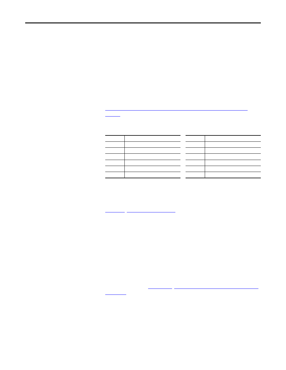
If all available I/O is not used, the image is truncated. The image always uses
consecutive words starting at word zero.
CompactLogix Controller I/O Image for PowerFlex 520-Series Drives on
page 48
shows the I/O image when using all of the 16-bit Datalinks.
CompactLogix Controller I/O Image for PowerFlex 520-Series Drives
Single drive mode is the typical configuration, where one node consists of a
PowerFlex 525 drive with a 25-COMM-D adapter.
For Multi-Drive mode, where one node can consist of up to 5 drives, see
Using Logic Command/Status
The Logic Command is a 16-bit word of control data produced by the controller
and consumed by the adapter. The Logic Status is a 16-bit word of status data
produced by the adapter and consumed by the controller.
When using a CompactLogix/ControlLogix controller, the Logic Command
word is always INT 0 in the output image and the Logic Status word is always
INT 0 in the input image.
This manual contains the bit definitions for compatible products available at the
time of publication in
Logic Command/Status Words: PowerFlex
.
Using Reference/Feedback
The Reference is a 16-bit INT (integer) produced by the controller and
consumed by the adapter. The Feedback is a 16-bit INT produced by the adapter
and consumed by the controller.
(16-bit Logic Command/Status, Reference/Feedback, and Datalinks)
INT
Output I/O
INT
Input I/O
0
Logic Command
0
Logic Status
1
Reference
1
Feedback
2
Datalink 1
2
Datalink 1
3
Datalink 2
3
Datalink 2
4
Datalink 3
4
Datalink 3
5
Datalink 4
5
Datalink 4