System wiring, Understanding the i/o image, System wiring understanding the i/o image – Rockwell Automation 25-COMM-D PowerFlex 525 DeviceNet Adapter User Manual
Page 71
Rockwell Automation Publication 520COM-UM002A-EN-E - April 2013
71
Using Multi-Drive Mode
Chapter 7
•
Automatic Device Replacement (ADR) cannot be used with any of the
drives.
•
The RSNetWorx Parameter editor cannot be used to access the
Host
parameters. It can only access the parameters on the DeviceNet adapter.
•
Since the RS-485 ports are used for daisy-chaining the drives, there is no
connection for a peripheral device such as a HIM or USB converter
module (1203-USB). DSI Splitter cables cannot be used to add a second
connection for a peripheral device.
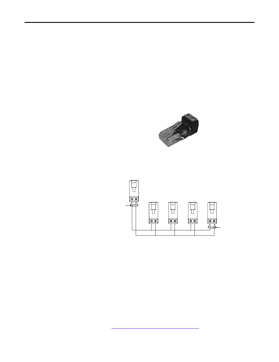
System Wiring
To daisy-chain the drives of the PowerFlex 525, the AK-U0-RJ45-TB2P terminal
block connector can be used for easy installation.
The wiring diagram for using AK-U0-RJ45-TB2P terminal block connectors is
shown below.
The AK-U0-RJ45-TB2P comes with (5) terminal block connectors and (2)
terminating resistors.
Understanding the I/O Image
The terms
input and output are defined from the scanner’s point of view.
Therefore, Output I/O is data that is output from the scanner and consumed by
the adapter. Input I/O is status data that is produced by the adapter and
consumed as input by the scanner.
The I/O image table will vary based on the configuration of
Host parameters
C169 [MultiDrv Sel]
and C175 [DSI I/O Cfg]. The image table always uses
consecutive words starting at word 0.
The
Multi-Drive Example of I/O Image on page 72
for an illustration of the
Multi-drive I/O image with 16-bit words.
To PowerFlex 525 with
DeviceNet adapter
To Drive #2
To Drive #3
To Drive #4
To Drive #5
120
Ω
, 1/4 W
resistor
120
Ω
, 1/4 W
resistor