Rockwell Automation 25-COMM-D PowerFlex 525 DeviceNet Adapter User Manual
Page 37
Rockwell Automation Publication 520COM-UM002A-EN-E - April 2013
37
Configuring the I/O
Chapter 4
7.
Edit the following:
8.
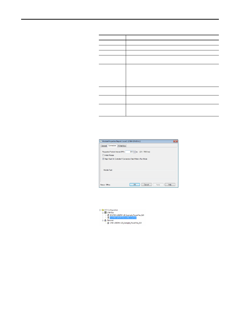
Click OK. The Module Properties Report window now appears. In the
Connection tab, set the appropriate Requested Packet Interval (RPI) for
your application.
9.
Click OK. The scanner is now configured for the DeviceNet network,
added to the RSLogix 5000/Logix Designer project, and appears in the
I/O Configuration folder.
In our example, a 1769-SDN scanner appears under the I/O
Configuration folder with its assigned name. For convenience, keep the
project open. Later in this chapter the project will need to be downloaded
to the controller.
Box
Setting
Name
A name to identify the scanner.
Description
Optional – description of the scanner.
Slot
The slot of the DeviceNet scanner in the rack.
Revision
The minor revision of the firmware in the scanner. (You already set the major revision
by selecting the scanner series in step 7.)
Electronic Keying
Compatible Keying. The “Compatible Keying” setting for Electronic Keying verifies
that the physical module is consistent with the software configuration before the
controller and scanner make a connection. Therefore, ensure that you have set the
correct revision in this window. See the online Help for additional information on this
and other Electronic Keying settings. If keying is not required, select “Disable Keying.”
“Disable Keying” is recommended.
Input Size
The size of the input data for the DeviceNet scanner. We recommend the default value
of 90.
Output Size
The size of the output data for the DeviceNet scanner. We recommend the default
value of 90.
Open Module
Properties
When this box is checked, clicking OK opens additional module properties dialog
boxes to further configure the scanner. When unchecked, clicking OK closes the
scanner’s New Module dialog box. For this example, uncheck this box.