Viewing and clearing events – Rockwell Automation 25-COMM-D PowerFlex 525 DeviceNet Adapter User Manual
Page 88
88
Rockwell Automation Publication 520COM-UM002A-EN-E - April 2013
Chapter 8
Troubleshooting
Viewing and Clearing Events
The adapter has an event queue to record significant events that occur in the
operation of the adapter. When such an event occurs, an entry consisting of the
event’s numeric code and a timestamp is put into the event queue. You can view
the event queue using the PowerFlex 22-HIM-A3/-C2S HIM or Connected
Components Workbench.
15
Drv 3 Logic Cmd
The present value of the Logic Command being transmitted to drive 3 (multi-drive mode)
by this adapter.
16
Drv 3 Reference
The present value of the Reference being transmitted to drive 3 (multi-drive mode) by
this adapter.
17
Drv 3 Logic Sts
The present value of the Logic Status being received from drive 3 (multi-drive mode) by
this adapter.
18
Drv 3 Feedback
The present value of the Feedback being received from drive 3 (multi-drive mode) by this
adapter.
19
Drv 4 Logic Cmd
The present value of the Logic Command being transmitted to drive 4 (multi-drive mode)
by this adapter.
20
Drv 4 Reference
The present value of the Reference being transmitted to drive 4 (multi-drive mode) by
this adapter.
21
Drv 4 Logic Sts
The present value of the Logic Status being received from drive 4 (multi-drive mode) by
this adapter.
22
Drv 4 Feedback
The present value of the Feedback being received from drive 4 (multi-drive mode) by this
adapter.
23
Input Size
The size of the input image in bytes transferred from the network to the drive.
24
Output Size
The size of the output image in bytes transferred from the drive to the network.
25
DL Fr Net 01 Val
The current datalink value being transmitted from this adapter to the drive (single drive
mode).
26
DL Fr Net 02 Val
The current datalink value being transmitted from this adapter to the drive (single drive
mode).
27
DL Fr Net 03 Val
The current datalink value being transmitted from this adapter to the drive (single drive
mode).
28
DL Fr Net 04 Val
The current datalink value being transmitted from this adapter to the drive (single drive
mode).
29
DL To Net 01 Val
The current datalink value being received from the drive by this adapter (single drive
mode).
30
DL To Net 02 Val
The current datalink value being received from the drive by this adapter (single drive
mode).
31
DL To Net 03 Val
The current datalink value being received from the drive by this adapter (single drive
mode).
32
DL To Net 04 Val
The current datalink value being received from the drive by this adapter (single drive
mode).
33
Opt Comm Errs
Number of errors that have been detected on the interface between the drive and the
adapter.
34
Net Rx Errs
The present value of the DeviceNet CAN Receive Error Counter register.
35
Net Rx Errs Max
The maximum value of the DeviceNet CAN Receive Error Counter register.
36
Net Tx Errs
The present value of the DeviceNet CAN Transmit Error Counter register.
37
Net Tx Errs Max
The maximum value of the DeviceNet CAN Transmit Error Counter register.
38
CAN Errors
The number of errors reported by the DeviceNet hardware that did not appear in [Net Rx
Errs Max] or [Next Tx Errs Max].
39
Boot Flash Count
The number of times the boot firmware in the adapter has been flash updated.
40
App Flash Count
The number of times the application firmware in the adapter has been flash updated.
41
Data Rate Sw
The present value of the data rate switches.
42
Net Addr Sw
The present value of the node address switches.
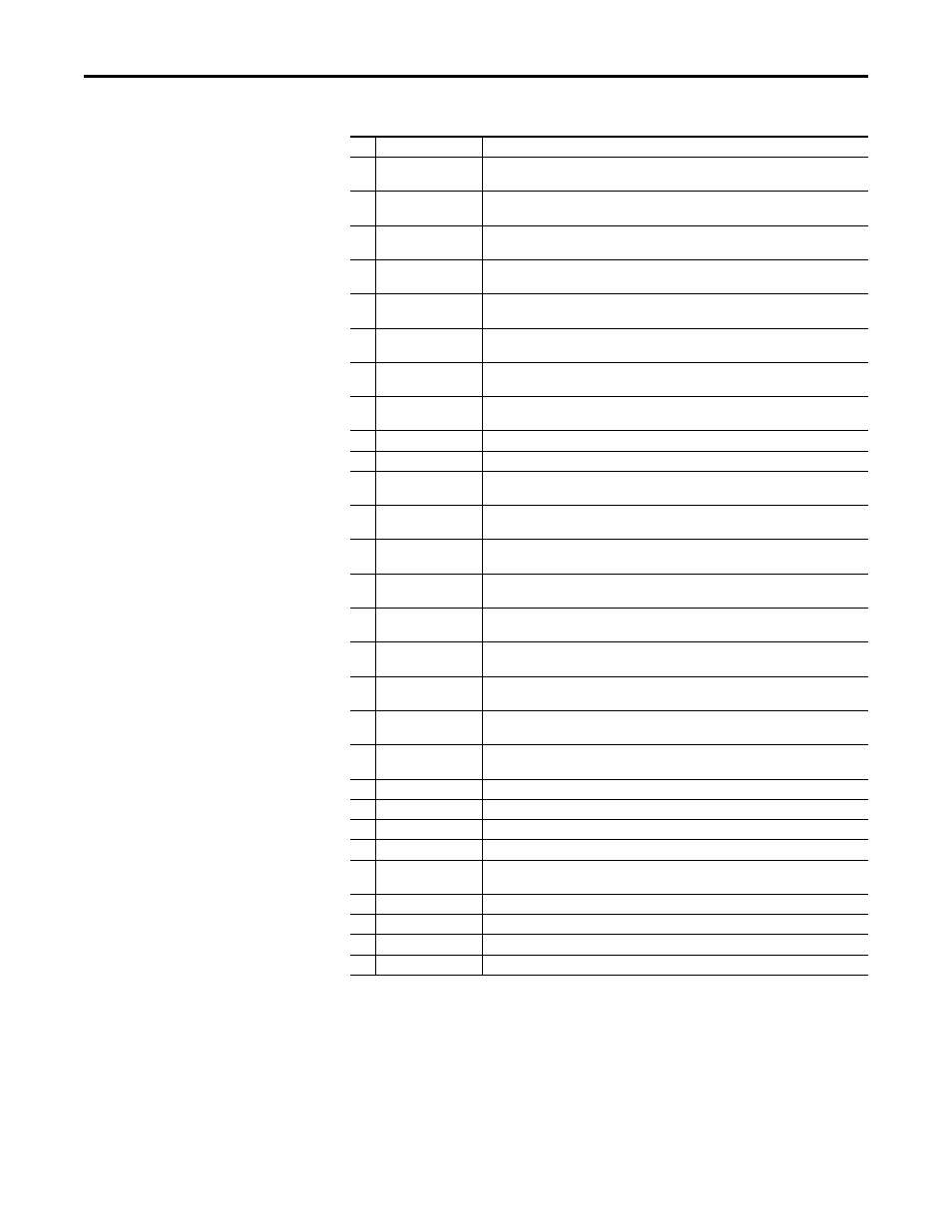
DeviceNet Adapter Diagnostic Parameters
No. Name
Description