Rockwell Automation 25-COMM-D PowerFlex 525 DeviceNet Adapter User Manual
Page 44
44
Rockwell Automation Publication 520COM-UM002A-EN-E - April 2013
Chapter 4
Configuring the I/O
If a Scanner Configuration dialog box appears, click Yes to continue. The
Edit I/O Parameters dialog box closes and then the 1769-SDN Scanlist
tab dialog box reappears.
20.
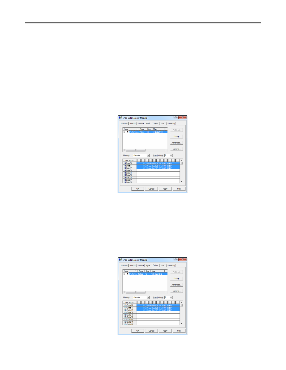
Click the Input tab to display the input registers for the 1769-SDN
scanner.
21.
Click AutoMap to map the drive input image to the 1769-SDN scanner as
shown in the example dialog box below.
22.
Click the Output tab to display the output registers for the 1769-SDN
scanner.
23.
Click AutoMap to map the drive output image to the 1769-SDN scanner
as shown in the example dialog box below.
24.
Click OK.
TIP
If your RSLogix 5000/Logix Designer project requires a different staring
DWord (double word, 32-bit) than the default value of ‘0’ for the drive
input image, set the Start DWord field to the appropriate value.
TIP
If your RSLogix 5000/Logix Designer project requires a different staring
DWord (double word, 32-bit) than the default value of ‘0’ for the drive
output image, set the Start DWord field to the appropriate value.