Rockwell Automation 25-COMM-D PowerFlex 525 DeviceNet Adapter User Manual
Page 59
Rockwell Automation Publication 520COM-UM002A-EN-E - April 2013
59
Using Explicit Messaging
Chapter 6
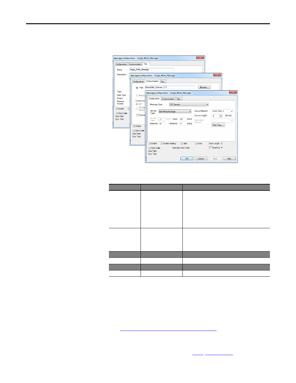
CompactLogix – Formatting a Message to Write a Single Parameter
Set Attribute Single Message Configuration Screens
The following table identifies the data that is required in each box to configure a
message to write a single parameter.
Configuration Tab
Example Value
Description
Message Type
CIP Generic
Used to access the DPI Parameter Object in the adapter.
Service Type
(1)
(1) The default setting for Service Type is “Custom,” enabling entry of a Service Code not available from the Service Type pull-down
menu. When choosing a Service Type other than “Custom” from the pull-down menu, an appropriate Hex. value is automatically
assigned to the Service Code box which is dimmed (unavailable).
Write Attribute Single
This service is used to Set a parameter value.
Service Code
(1)
10 (Hex.)
Code for the requested service.
Class
93
(4)
(4) See
Explicit Messaging Class Code Compatibility with PowerFlex 525 Drives on page 55
for limitations of PowerFlex 525 drives when
using DPI Parameter Object Class code 0x93 for explicit messaging.
Class ID for the DPI Parameter Object.
Instance
41 (Dec.)
Instance number is the same as parameter number.
(6)
(6) This applies only in single-drive mode. For Multi-drive mode, see
,
for examples.
Attribute
(2)
(2) Setting the Attribute value to “9” will write the parameter value to the drive’s Non-Volatile Storage (EEPROM) memory, so the
parameter value will remain even after the drive is power cycled. Important: When set to “9,” be very cautious as the EEPROM may
quickly exceed its life cycle and cause the drive to malfunction. Important: If you need to make frequent parameter changes using
Explicit Messages, set Host parameter C121 [Comm Write Mode] to 1 “RAM only”.
9 or A (Hex.)
Attribute number for the Parameter Value attribute.
Source Element
Accel_Time_1
(5)
(5) In this example, Accel Time 1 is a 16-bit parameter requiring the Data Type field to be set to “INT” when creating the controller tag.
Also, the Source Length field on the Message Configuration screen must correspond to the selected Data Type in bytes (for example,
2 bytes for an INT). See the drive documentation to determine the size of the parameter and its data type.
Name of the tag for any service data to be sent from the scanner
or bridge to the adapter/drive.
Source Length
2 bytes
Number of bytes of service data to be sent in the message.
Destination
–
Leave blank (not applicable).
Communication Tab Example Value
Description
Path
(3)
(3) Click Browse to find the path, or type in the name of the device listed in the I/O Configuration folder (for this example,
DeviceNet_Scanner). Then always type in a comma followed by a “2”, which is the DeviceNet scanner port, followed by another
comma, then followed by the DeviceNet node number of the drive (for this example, “1”).
DeviceNet_Scanner, 2, 1
The path is the route that the message will follow.
Tag Tab
Example Value
Description
Name
Single_Write_Message
The name for the message.