Compactlogix example scattered read request data – Rockwell Automation 25-COMM-D PowerFlex 525 DeviceNet Adapter User Manual
Page 64
64
Rockwell Automation Publication 520COM-UM002A-EN-E - April 2013
Chapter 6
Using Explicit Messaging
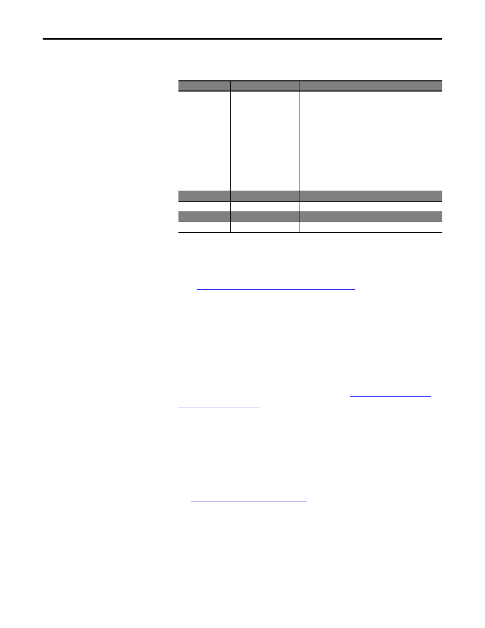
The following table identifies the data that is required in each box to configure a
message to read multiple parameters.
CompactLogix Example Scattered Read Request Data
In this message example, we use the data structure in
in the source tag named Scattered Read Request to read
these five 16-bit parameters in a PowerFlex 525 drive:
•
Host parameter b001 [Output Freq]
•
Host parameter b003 [Output Current]
•
Host parameter b004 [Output Voltage]
•
Host parameter b005 [DC Bus Voltage]
•
Host parameter b017 [Output Power]
DPI Parameter Object on page 117
(Class code 0x93) for parameter
numbering.
Configuration Tab
Example Value
Description
Message Type
CIP Generic
Used to access the DPI Parameter Object in the adapter.
Service Type
(1)
(1) The default setting for Service Type is “Custom,” enabling entry of a Service Code not available from the Service Type pull-down
menu. When choosing a Service Type other than “Custom” from the pull-down menu, an appropriate Hex. value is automatically
assigned to the Service Code box which is dimmed (unavailable).
Custom
Required for scattered messages.
Service Code
(1)
0x32 (Hex.)
Code for the requested service.
Class
93
(3)
(3) See
Explicit Messaging Class Code Compatibility with PowerFlex 525 Drives on page 55
for limitations of PowerFlex 525 drives when
using DPI Parameter Object Class code 0x93 for explicit messaging.
Class ID for the DPI Parameter Object.
Instance
0 (Dec.)
Required for scattered messages.
Attribute
0 (Hex.)
Required for scattered messages.
Source Element
Scattered_Read_Request
(4)
(4) In this example, we are reading five 16-bit parameters. Each parameter being read requires two contiguous INT registers. Therefore,
a controller tag was created with its Data Type field set to “INT[10].” Also, the Source Length field on the Message Configuration
screen must correspond to the selected Data Type in bytes (for this example, 20 bytes for an INT[10] array). Scattered read messages
always assume that every parameter being read is a16-bit parameter, regardless of its actual size. Maximum message length is 256
bytes which can read up to 64 parameters, regardless of their size.
Name of the tag for any service data to be sent from the scanner
or bridge to the adapter/drive.
Source Length
20 bytes
(4)
Number of bytes of service data to be sent in the message.
Destination
Scattered_Read_Response
(5)
(5) The controller tag for “Scattered_Read_Response” must be the same size as the controller tag for “Scattered_Read_Request” (for
this example, 20 bytes), but can be a different data type.
The tag where the data that is read is stored.
Communication Tab Example Value
Description
Path
(2)
(2) Click Browse to find the path, or type in the name of the device listed in the I/O Configuration folder (for this example,
DeviceNet_Scanner). Then always type in a comma followed by a “2”, which is the DeviceNet scanner port, followed by another
comma, then followed by the DeviceNet node number of the drive (for this example, “1”).
DeviceNet_Scanner, 2, 1
The path is the route that the message will follow.
Tag Tab
Example Value
Description
Name
Scattered_Read_Message
The name for the message.