Compactlogix example – Rockwell Automation 25-COMM-D PowerFlex 525 DeviceNet Adapter User Manual
Page 51
Rockwell Automation Publication 520COM-UM002A-EN-E - April 2013
51
Using the I/O
Chapter 5
CompactLogix Example
Creating Ladder Logic Using the Logix Designer Generic Profile (all
versions)
Adapter Parameter Settings for CompactLogix Controller Example
These adapter settings were used for example ladder logic program in this section.
Controller Tags
When you add the adapter and drive to the I/O configuration (
), Logix
Designer automatically creates generic (non-descriptive) controller tags. In this
example program, the following controller tags are used.
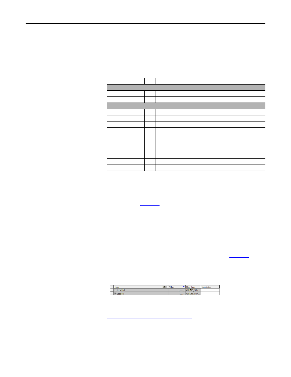
CompactLogix Controller Tags for Drive Generic Profile Ladder Logic Program Example
You can expand the Output and Input tags to reveal the output and input
configuration (see
CompactLogix Controller Tags for Drive Generic Profile
Ladder Logic Program Example on page 51
). For this example, the Input tag
requires three 32-bit words of data and the Output tag requires three 32-bit
words of data. This corresponds to six 16-bit words of data for input and six 16-
bit words of data for output because the 1769-SDN is a 32-bit device.
Parameter
Value Description
Adapter Device Parameters
02 [DLs From Net Cfg]
4
Sets the number of Datalinks used to write data from the network controller.
04 [DLs To Net Cfg]
4
Sets the number of Datalinks used to read data to the network controller.
Adapter Host Parameters
P046 [Start Source 1]
4
Sets the input for [Start Source 1] to 4 “Network Opt”
P047 [Speed Reference1]
4
Sets the input for [Speed Reference1] to 4 “Network Opt”
C161 [Opt Data In 1]
52
Points to drive parameter P052 [Average kWh Cost]
C162 [Opt Data In 2]
41
Points to drive parameter P041 [Accel Time 1]
C163 [Opt Data In 3]
42
Points to drive parameter P042 [Decel Time 1]
C164 [Opt Data In 4]
410
Points to drive parameter A410 [Preset Freq 0]
C165 [Opt Data Out 1]
45
Points to drive parameter P045 [Stop Mode]
C166 [Opt Data Out 2]
41
Points to drive parameter P041 [Accel Time 1]
C167 [Opt Data Out 3]
42
Points to drive parameter P042 [Decel Time 1]
C168 [Opt Data Out 4]
410
Points to drive parameter A410 [Preset Freq 0]
TIP
The PowerFlex 525 drive supports up to three control functions and three
Reference functions. There are several parameters in the drive that will
override the start source and speed reference command if enabled. For details
on these parameters, see the PowerFlex 525 drive’s user manual, publication
The Host parameters [Opt Data Out 1...4] are inputs into the drive that come
from controller outputs (data to write a drive parameter). The Host parameters
[Opt Data In 1...4] are outputs from the drive that go to controller inputs (data
to read a drive parameter).