Emergency operations – SkyTrak 3606 Operation Manual User Manual
Page 86
84
3606 Rev 11/99
Emergency Operations
2. Block all four wheels to prevent the vehicle from moving once the
parking brake is disabled.
3. Position the towing vehicle in place. Attach any chains needed to
secure the disabled vehicle.
4. An 8mm allen head socket and torque wrench will be needed to
properly disable the parking brakes. Scribe a line on the socket so
you can accurately count the number of turns each bolt makes as
you perform the procedure.
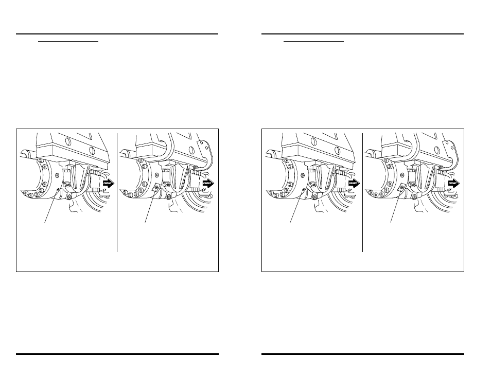
5. Crawl under the front axle and locate the six brake release bolts
(three bolts per side) at the base of the front axle (Figure 53). Clean
the six bolt recesses of any dirt or debris.
Figure 53
6. Alternately turn brake release bolts A, B & C inward (clockwise)
until you begin to feel resistance (Figure 54). This will take approxi-
mately two or three turns.
7. Using a torque wrench, alternately turn bolts A, B & C inward 1/2
turn until a torque of 22 lb/ft (30 Nm) is reached.
8. Again, using the torque wrench, alternately turn bolts A, B & C
inward until a minimum torque of 30 lb/ft (41Nm) is reached. This
will take approximately 1/2 turn. Do not exceed 50 lb/ft (68 Nm).
One of the Six
Brake Release Bolts
Located in the Front Axle
OS2200
One of the Six
Brake Release Bolts
Located in the Front Axle
EARLY PRODUCTION
CURRENT PRODUCTION
84
3606 Rev 11/99
Emergency Operations
2. Block all four wheels to prevent the vehicle from moving once the
parking brake is disabled.
3. Position the towing vehicle in place. Attach any chains needed to
secure the disabled vehicle.
4. An 8mm allen head socket and torque wrench will be needed to
properly disable the parking brakes. Scribe a line on the socket so
you can accurately count the number of turns each bolt makes as
you perform the procedure.
5. Crawl under the front axle and locate the six brake release bolts
(three bolts per side) at the base of the front axle (Figure 53). Clean
the six bolt recesses of any dirt or debris.
Figure 53
6. Alternately turn brake release bolts A, B & C inward (clockwise)
until you begin to feel resistance (Figure 54). This will take approxi-
mately two or three turns.
7. Using a torque wrench, alternately turn bolts A, B & C inward 1/2
turn until a torque of 22 lb/ft (30 Nm) is reached.
8. Again, using the torque wrench, alternately turn bolts A, B & C
inward until a minimum torque of 30 lb/ft (41Nm) is reached. This
will take approximately 1/2 turn. Do not exceed 50 lb/ft (68 Nm).
One of the Six
Brake Release Bolts
Located in the Front Axle
OS2200
One of the Six
Brake Release Bolts
Located in the Front Axle
EARLY PRODUCTION
CURRENT PRODUCTION